The STGPT system provides a completion where the gravel packing and the acid treatment of a zone can be performed in a single workstring trip.
Jay Shivers and Jack Haynes, Shell; Tom Roane and Kevin Serrette, Halliburton
Over the past few years, there have been substantial advancements in sand control technology that have led to increased production and earlier revenue generation. Many of these advancements are individual technologies, while others consist of several new technologies that have been combined.
A new Single-Trip, Gravel-Pack-and-Treat (STGPT) system that reduces cycle times and, thus, costs has been developed. The system is designed to limit fluid losses to the formation; eliminate pipe trips without a fluid-loss device on seat; allow a fluid-loss device to be functional before, if necessary, and after the placement of acid across the formation; and allow greater safety and well control. When using this system, the operator also can realize reduced formation exposure, and increased well-control safety. These advantages result in a reduction in operational time when compared to traditional gravel-packing and acidizing operations.
INTRODUCTION
Shell’s Bonga Field is located in the OML 118 Block 60 mi off the southern coast of Nigeria in a water depth of 3,000–3,500 ft. In Phase I of the project, 16 wells—nine producers and seven injectors—were batch drilled and completed. The design criteria for these wells targeted a 20-yr life span with a production capacity for 40,000 bopd and 60,000-bpd injection. The final design of the wells called for 10 frac packs (seven injectors and three producers), five openhole horizontal gravel pack producers and one stand-alone screen producer. Most of the reservoirs required sand control due to potential fines migration. Alternate path technology was used in the cased-hole wells due to the potential for voids in the pack. The temporary abandonment procedures called for the wells to have a deep-set, hydraulically operated ball valve, a Surface-Controlled Subsurface Safety Valve (SCSSV) and a hanger plug. All of the producing wells were unloaded at the rig. Two injection wells were unloaded to the rig due to having a CaCO3 pill on the screens because of fluid loss. The remainder of the injectors had plugs pulled after tree installation and the ball valves opened via formation saver valves; then, injection was established from the host.
Bonga Phase I had many problems, primarily fluid loss. One well had an immediate fluid loss of 1,200 bbl/hr. This resulted in possible risk of formation damage and, subsequently, the cost to mitigate this risk. Another issue encountered was stuck wash pipe during a stimulation run that resulted in excess rig time due to fishing operations. The main cause of the wash pipe sticking was debris that had fallen downhole after the gravel pack treatment was completed. These problems could have been avoided if an STGPT system had been used.
PLANNING
With the elevated expense of an operation of this nature, the learning curve must take place prior to the event.
Several obstacles for this case needed to be resolved. The hole angle of 45° would present a degree of difficulty not seen in a horizontal or vertical completion. Also, the fact that it would be an openhole completion would require careful consideration concerning hole support needed by a pressure maintenance system.
The tool system’s complexity increases with the implementation of the single-trip, gravel-pack-and-acidize functionality. Earlier technology required the gravel pack and the acid treatment to be carried out with at least two pipe trips. The service tool had to be retrieved after the gravel pack was completed, and a wash string would be run on a second trip to accomplish this.
In spite of an increased degree of difficulty, STGPT systems are successfully employed today within the designated operating envelopes; however, key activities such as thorough and accurate operational procedures and pre-job overviews must be conducted if a successful completion is to result.1–5
APPLICATIONS
The openhole environment is less forgiving than that in cased-hole applications. The fact that the openhole interval had an approximate 45° deviation added another measure of difficulty to the task.
Most openhole completions are performed when the hole angle is at 90°, or near horizontal. In a horizontal openhole gravel pack, the pumping process nearly always involves depositing the proppant in an alpha-beta wave principal. Using the alpha-beta method, the first 80% of the open hole is filled in a layered process, in a progression from heel to the toe. The second stage of the process fills the upper 20% of the hole from toe. This process uses gravity to pull the sand to the bottom of the hole ID.
To a lesser degree, some openhole completions are performed when the hole angle is at 0°, or near vertical. In a vertical openhole gravel pack, the pumping process will take advantage of gravity to deposit the proppant in the more conventional way, which is to fill the open hole completely in the direction of toe to heel.
The methods used on the deviated openhole gravel pack are not as conventional. The individuals designing the procedure must take into account that gravity is working to pull the proppant to both the bottom of the hole ID and toward the toe simultaneously. This adds a degree of difficulty to either of the two previously mentioned methods. It is imperative that the deposition rate of proppant not exceed the rate at which gravity pulls the proppant to the toe of the well so that the bore or the hole ID does not become blocked. Otherwise, the proppant will try to stack up inside the diameter of the hole, before it can slide toward the toe, resulting in a blocked path and a resultant incomplete pack.
This system can perform on shallower wellbores in which the main drivers may include well control, reduced formation damage and enhanced operational safety rather than the cost-reduction benefit.
DRIVERS
After the proppant has been placed in the open hole and around the screen, it is advantageous to place a delayed breaking acid across the formation and close the fluid-loss device before the acid breaks the filter cake. While the delayed acid is reacting to remove the filter cake, the service tools can be retrieved from the well, and preparations for the uphole completion can begin. The fluid-loss device will protect the formation from high fluid loss after the filter cake has been removed. This also alleviates concerns of formation degradation caused by fluid loss to the formation.
STGPT SERVICE TOOL
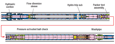
The new system combines gravel packing and treating into a single workstring trip, Fig. 1. Applications for this enhanced system include openhole gravel packs where the option to flow back or well test is not available, and openhole gravel packs where the need to maximize filter cake removal through stimulation exists. To accomplish these objectives, a version of the tool was developed that included two additional flow-diversion sub assemblies and additional interval-isolation tool components.
 |
|
Fig. 1. The STGPT service tool.
|
|
The assembly requires additional components to be added or designed into the gravel-pack service tool. These additional components provide flow paths that control the weight-down washdown circulation, provide for a packer testing position with fluid circulation into the open hole, shut off circulation through the actuated reverse ball seat, and reopen that path prior to final reverse circulation and actuation.
MAIN COMPONENTS
Some of the components are new to STGPT completions and others have been adopted from older technologies but are still required. Listed below are the more recent developments.
The hydraulic section is designed with an isolation sleeve to isolate the packer setting ports during circulation. It can be opened later to set the packer. The internal isolation sleeve will isolate the setting piston from the pressure created from circulation. When the circulation is complete and it is time to set the gravel-pack packer, a setting ball is dropped from the surface. An initial pressure of about 500 psi will shift the isolation sleeve down, exposing the setting ports. As the sleeve shifts down, the isolation-sleeve ID opens up and releases the setting ball, which, in turn, drops down to the hydro-trip sub/tapered ball seat below the crossover.
The hydro-trip sub (Fig. 2) provides a means for washing through the multi-position tool as it is run, but prohibits circulation back up the return path to the casing. Instead, the circulation flow down the workstring is directed down through the washpipe. The internal flow path is sealed off when the packer setting ball lands on the tapered seat. With about 1,000-psi pressure on the workstring, the seat shears down to isolate flow in the internal flow path and direct the flow to the crossover slurry ports. At the same time, the shifting will open the return flow path through the crossover return circulation flow path into the casing.
 |
|
Fig. 2. The STGPT’s hydro-trip sub.
|
|
Packer test assembly. After the hydro-trip sub is activated, there is an open path down the casing to the washpipe. Pressure must be applied down the casing to test the packer elements against the casing. The Packer Test Assembly (PTA) was required in the case-history well operations to serve as a temporary plugging device to prohibit the pressure from going down the casing, Fig. 3. To accomplish this, a ball against which pressure must be applied is placed on seat in the PTA.
 |
|
Fig. 3. Packer test assembly.
|
|
After the packer is set fully and the service tool is sheared or rotated off the packer, the service tool is picked up until the PTA is pulled against the lower seal bore of the closing sleeve to a pre-determined shear value. When sheared, the internal ball will be placed on seat, blocking the annulus path. Pressure can be applied down the casing and into the return flow ports to test the gravel-pack packer. After a successful test, additional pressure is added to shear the ball seat, opening the annulus pathway once again.
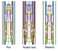
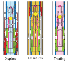
Pressure-activated ball check. After the gravel-pack treatment, a similar change must be made in the lower end of the service tool. After gravel packing, the return flow is typically blocked by a check-valve device to allow the well to be reversed out. In order to circulate down the washpipe, some means of opening up the tool to flow had to be incorporated to allow completion of the treating flow path. The Pressure-Activated Ball Check (PABC) provides this capability through its internal ball check, Fig. 4. Similar to the packer test assembly, the ball check is set on seat by pulling it against the lower seal bore of the closing sleeve to a pre-determined shear value. When sheared, the internal ball will be placed on seat, blocking the annulus path during reverse circulation. After a successful reverse-out operation, and prior to the acid stimulation treatment, the PABC is picked up above the packer, and annulus pressure is added to shear the ball seat. This action opens the annulus pathway once again.
|
|
|
Fig. 4. The pressure-activated ball check.
|
|
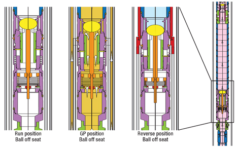
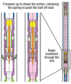
Flow diversion sleeve. The treating sleeve is shown in the figure below in the “run” position with the respective flow paths indicated. To convert the tool to a treating mode, a second ball is dropped from the surface to plug the tapered seat of the treating sleeve and shift it downward, changing the flow paths within the tool. In essence, once the flow-diversion sleeve (Fig. 5) is activated, the pathway for fluid originated from the workstring is diverted down the washpipe as opposed to the casing. This converts the service tool to the treating position.
|
|
|
Fig. 5. The flow diversion sleeve activation; fluid pathway is diverted, converting tool to the treating position.
|
|
Hydrostatic control valve. One final tool (not used on this project but generally beneficial to the placement operation) is a Hydrostatic Control Valve (HCV). This is a downhole pressure regulator that maintains a hydrostatic column of fluid in the workstring when the bottomhole pressure drops off as well stimulation begins. This enables the acid placement to be controlled to a specific volume by stopping the pumping operations; at this point, the valve closes and stops the injection of fluids. Also included in this tool is a check valve to stop the well from flowing back after stimulation. This is especially useful when the treating fluids are lighter than the completion brine. The HCV is dropped from the surface and locates in a special receptacle in the workstring above the gravel-pack packer.
PRESSURE MAINTENANCE
Maintaining a fluid hydrostatic overbalance on the formation is critical to maintaining hole stability and performing a successful gravel-packing operation. Removing the fluid hydrostatic overbalance, even for a few seconds, can allow the filter cake to lift off, creating additional fluid loss and/or allowing the open hole to collapse.
What follows is the basic process used to maintain constant hydrostatic pressure on the formation until the gravel-pack treatment is in place and serving as formation support.
While running the gravel pack assembly in, there will be communication to the formation from the casing annulus above the packer (around the unset packer) and the workstring to the formation through the workstring and out the float shoe or bottom of the washpipe.
Once the packer setting ball is on seat to set the packer, there will be communication to the formation from the casing annulus above the packer (around the unset packer). After the ball has moved to the tapered ball, and the tapered seat has shifted down, there will be communication to the formation from the casing annulus above the packer around the unset packer and the casing annulus above the packer through the communication port and down through the micro-annulus of the crossover.
After the packer has been set, there will be communication to the formation from the casing annulus above the packer through the communication port and down through the micro-annulus of the crossover. After the service tool has been picked up to the new weight-down position, there will be communication to the formation from the casing annulus above the packer through the communication port and down through the micro-annulus of the crossover and down the workstring and out the crossover and closing sleeve.
After the packer test tool has been picked up to activate the packer test-tool ball seat, there will be communication to the formation down the workstring and out the crossover and closing sleeve. After the packer test tool has been sheared, there will be communication to the formation down the workstring and out the crossover and down the casing annulus above the packer through the communication port and down through the micro-annulus of the crossover, and through the screen.
To summarize, there will be communication from the annulus to the formation around the packer until the packer is set, and from the annulus through the communication port and down through the micro-annulus until the MPW is picked up for the packer test. At this time, however, the communication to the formation down the workstring already will have been re-opened, because the crossover will have been moved out of the sealbore and across the closing sleeve ports.
PROCEDURE
The standard procedure used for the openhole single-trip gravel-pack system is as follows. First, drill and case the hole with Oil-Based Mud (OBM). Next, circulate and swap all OBM to non-solids-free Water-Based Mud (WBM), followed by soaps and chemicals. The WBM will be used as the openhole Drill-In Fluid (DIF). Run a bit and scraper with casing brushes while pumping flushes to clean and dislodge any debris, scale and emulsions on the casing wall. Then, drill the openhole section with WBDIF.
After reaching TD and confirming that hole and cutting are sufficiently circulated back to surface, it is recommended to stop the pumps and make a “short trip” from TD to the casing shoe and back to TD. This is to check the integrity of the open hole to provide assurance that the hole is not trying to collapse. It is recommended that a separate hole opener run be made to check the integrity of the open hole. Sometimes, only a check trip will be done with the drilling BHA. Once the hole opener or check trip is at TD, two openhole volumes of clean solids-free WBDIF will be circulated in and left in the openhole section.
Pick up to about100 ft above the casing shoe and displace the casing with sweeps, followed by filtered completion brine. Pull out of the hole. (Note: At this time, the only solids in the hole should the thin layer on the openhole wall.) Run in hole with the gravel-pack assembly. Use washpipe with an OD that is 80% or more of the screen ID. Position the end of the assembly near TD, verifying with the drill pipe measurements. Measure, record and report the 10-min. fluid loss rate in bbl per hour.
Rig up pump-in lines and test the lines to 2,500 psi. Displace the solids-free DIF from the well with completion fluid by pumping down the workstring a minimum of one hole volume at 1 to 2 bbl/min. Do not exceed friction pressure of 1,000 psi (friction pressure measured prior to running the screen into the open hole). Start measuring turbidity every 20 bbl of returns after receiving bottoms up. Continue circulating until returns are consistently less than 20 NTU. Record fluid lost after each 20 bbl pumped.
Drop the packer setting ball and allow time to get to the packer (5 min./1,000 ft). Rig up the pump lines and test lines to 5,000 psi. Begin pumping until the ball goes on seat. Apply about 500 psi. The ball will shear the isolation sleeve and move to the tapered ball seat.
Apply 1,500 psi. This will provide a good setting of the ball in the tapered seat. Hold pressure for 3 min. Bleed off pressure, pull 10,000 lb over pickup weight to verify that the packer has started to set. Slack off 6,000 lb and pressure to 2,000 psi for 3 min. Stage up to 2,500 psi, 3,000 psi and, then, 3,500 psi. Bleed off the pressure.
Rotate to the right with neutral weight at the packer to release the running tool acme thread (less than 12 rounds at the packer). Pick up the assembly to activate the packer test assembly. This places the ball of the packer test assembly on seat, which blocks communication from the tubing-casing annulus to the formation.
Drop down to the circulating position and test the packer with pressure on the annulus by closing the BOP. After the successful test, continue to pressure up to shear the packer test assembly. This will open the washpipe up to the casing annulus. Pick up to reverse position and pickle the workstring.
Move the service tool back to the circulate position and perform the circulation rate test at rates of 0.5, 1, 2, 3, 4, 5, 6 and 7 bbl/min. (based on design) by pumping down the drill pipe and up the annulus. Do not circulate above frac gradient. Pump horizontal gravel pack as per the program. After the gravel-pack treatment is finished, reverse out excess slurry from the drill pipe. Pull the drill pipe and service tool out of the well, closing the fluid loss device.
SUMMARY
The new tool options now available have made it possible to successfully perform gravel-pack-and-treat operations with a single trip into the hole. This capability provides an operator with significant savings in openhole well completions that include some sort of post-gravel-pack treating operations.
The STGPT system can provide a completion in which the gravel packing and the acid treatment of each zone can be performed in the same trip. This configuration limits fluid loss to the formation, does not require a fluid-loss device on seat, allows a fluid-loss device to be functional before and after the placement of acid across the formation, increases safety and well control, and reduces formation exposure. 
ACKNOWLEDGMENTS
This article was adapted from a paper presented at the Mediterranean Offshore Conference, Alexandria, Egypt, May 20–22, 2008.
REFERENCES
1 Marple, B., Griffith, F. and D. Oneal, “Successful completions in the Gulf of Mexico using the single trip perf-pack tool system,” OTC 8583 presented at the 1998 Offshore Technology Conference, Houston, May 4, 1998.
2 Oneal, D. S., “Texaco single-trip case histories,” Halliburton Energy Services, Inc., Lafayette, Louisiana, June 18, 1997.
3 Grigsby, T., “Single-trip advanced completion systems,” Halliburton Energy Services, Inc., Lafayette, Louisiana, June 18, 1997.
4 Jones, R., “Single trip perforating/gravel pack system reduces formation damage in offshore Gulf of Mexico wells: Case histories and guidelines for candidate selection,” SPE 54285 presented at the SPE Asia Pacific Oil and Gas Conference and Exhibition, Jakarta, Indonesia, April 20–22, 1999.
5 Jannise, R. C. and W. J. Edwards, “Innovative method for predicting downhole pressures during frac-pack pumping operations facilitates more successful completions,” SPE 109837 presented at the SPE Asia Pacific Oil and Gas Conference and Exhibition, Jakarta, Indonesia, Nov. 1–Oct. 30, 2007.
|
THE AUTHORS
|
| |
Jay Shivers worked in the industry for four years prior to enrolling at Texas A&M University, where he earned a BS in petroleum engineering in 1991. He has worked for Shell since 2001, first on the NaKika deepwater development project in the Gulf of Mexico as a Completion Engineer, then as the Senior Completion Engineer for the last 51⁄2 years on the Bonga deepwater development in Lagos, Nigeria. Prior to Shell, he worked for Baker Corp., Coastal Oil and Gas/El Paso Corp., and New Tech Engineering.
|
|
| |
Tom Roane is Global Advisor–Sand Control for Halliburton. He received his degree in engineering from Texas Tech University. Mr. Roane has been with Halliburton since 1975 in various positions. The bulk of his experience has been on the technical and operations aspect of downhole completion equipment.
|
|
| |
Kevin Serrette is Technical Advisor-Sand Control/Completions for Halliburton. He received his degree in petroleum engineering from the University of Southwestern Louisiana. Mr. Serrette has been with Halliburton since 1978 in various positions.
|
|


