Advances are being delivered in multiphase pumping, water treatment and injection, separation and compression systems designed for the seafloor.
Jeanne M. Perdue, Contributing Editor
Subsea processing technology has done much to unlock the deepwater reserves in the UK, and this technology is making its way to Brazil and other deepwater plays. By placing the separators, pumps and injectors on the seafloor, offshore operators are better able to anticipate production volumes at topsides, improve overall reservoir recovery, debottleneck offshore facilities experiencing high watercuts and develop marginal fields surrounding a hub platform. This article presents a roundup of some of the latest technologies for subsea solid-liquid-gas separation, subsea multiphase pumping and subsea water injection.
HEAVY OIL SEPARATION AND WATER REINJECTION
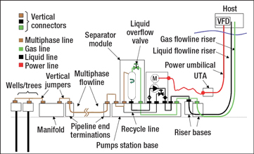
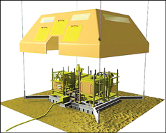
FMC Technologies Inc. has been awarded a $90 million contract by Petrobras to supply a subsea separation system for the mature Marlim Field, located in the Campos Basin, offshore Brazil. The subsea separation module will separate heavy oil (20°API), natural gas, sand and water at a water depth of 2,950 ft (900 m). The system will apply FMC’s novel pipe separator design, licensed and developed in cooperation with StatoilHydro, Fig. 1. The separation system also includes cyclone modules that will perform water treatment before reinjecting the water back into the reservoir.
 |
|
Fig. 1. artist’s rendition of FMC Technologies’ subsea pipe separator and water reinjection skid for Marlim Field offshore Brazil.
|
|
This will be the first deepwater deployment of subsea separation technologies in a mature field, and the world’s first separation of heavy oil and water in a subsea environment. It will also be the first separation system to include subsea reinjection of water into the reservoir to boost production. It will have a vertical connection system and will be capable of operating at pressures up to 5,000 psi and temperatures up to 176°F (80°C).
“Marlim is the fifth field in the world that will utilize FMC’s subsea separation technologies,” said Tore Halvorsen, senior vice president of FMC Technologies’ Global Subsea Production Systems division. “The project will enable a broader application of our separation technologies for future subsea processing opportunities.”
The basic pipe separator design, used for low-pressure production at Troll B offshore Norway, has a small diameter and short residence time, and operates based on the difference between oil-phase and aqueous-phase flowrates. The shear force at the interface between the two layers breaks any emulsion formed.
The Marlim system will be jointly engineered by FMC staff located in Brazil, Norway and the Netherlands. Final manufacturing and integration activities will be performed at the company’s Rio de Janeiro facility, with deliveries projected to begin in 2011. The contract also includes topside and subsea controls, tooling and skids, a water injection pump system, a complete technology and qualification program for separation and processing equipment validation, systems integration testing, offshore commissioning and technical assistance for installation.
SIMPLIFIED SUBSEA SEPARATION AND PUMPING
Shell Technology Norway Subsea AS is working with Sulzer Pumps to design a gas/liquid separation and pumping unit that provides an effective means of artificial lift for subsea oil fields. One key feature of this gas-tolerant system will be elimination of the need for active subsea control valves, in order to reduce the complexity of both the subsea facilities and the control system.
“Compared to multiphase pumping, the energy efficiency may be improved by a factor of two to four, depending on the water depth,” said Svein Håheim, senior subsea engineer for Shell Technology Norway. “A subsea separation and pumping system is, however, more challenging to operate, as the liquid level in the separator needs to be controlled to ensure a stable liquid feed to the pump. The pump must also either be protected from gas surges or designed to be gas tolerant. For deepwater applications, this becomes even more challenging, as compact separation solutions are required, due to the difficulty of manufacturing subsea separators to withstand the high hydrostatic pressure.”
The conceptual design has been completed (Fig. 2), and model testing of the subsea hybrid helicoaxial-radial pump has been carried out at suction pressures up to 435 psi (30 bar). The slug handling and control strategy was verified by model testing, and the apparatus was found to be capable of handling any realistic slug size and frequency. Tests showed that control system response time of 1–2 s is required to handle typical slug frequencies, which is well within the capabilities of today’s subsea control systems and variable speed drives.
 |
|
Fig. 2. The conceptual design for Shell’s subsea hybrid helicoaxial-radial pump.
|
|
MULTIPHASE PUMP FOR DEEPWATER CAMPOS BASIN
On Sept. 17, 2009, Petrobras signed a technological cooperation agreement with Norwegian firm Framo Engineering to install the first deepwater multiphase pumping system in the Campos Basin in Brazil. The prototype, which pumps multiphase fluids (oil, water and gas) from the well to the platform, will be the world’s first helicon-axial-type pump to exert differential pressure above 850 psi.
At the signing ceremony held at the main Petrobras office in Rio de Janeiro, Framo commercial director Jon Arve Svaeren noted that this is the first time this technology will be applied in Brazil and in deep waters. The device is expected to be installed in Barracuda Field in the second half of 2011. It is intended to operate in a satellite well of platform P-48 in water depths of about 1,040 m.
Subsea multiphase pumping systems can reduce the high backpressure on producing wells, thereby increasing oil production and improving the recovery factor. Multiphase pumps make production feasible for wells located far from production platforms, and may even eliminate extra production platforms in areas where there is already some infrastructure in place. In mature fields, watercuts and gas fractions usually increase over time, and this can be aggravated if produced fluids must be transported over long pipelines or across hilly topography to production platforms or process facilities. To avoid premature abandonment of such subsea producing wells, multiphase pressure boosting is implemented to extend production.
Framo’s rotodynamic (helicon-axial) multiphase pumping systems are capable of pumping multiphase flow streams with various combinations of oil, water and gas without the need for separation. Since its founding in 1982, Framo Engineering has delivered 25 subsea processing systems globally, which have logged more than 900,000 operating hours.
“Some may suggest this is in its infancy,” said Tony Laing, Framo UK general manager, “but to some subsea processing is a mature business.”
SUBSEA WATER TREATMENT
In March 2009, Aker Solutions and Well Processing AS signed a cooperation agreement to bring a new technology to market that combines subsea water treatment and injection to increase oil production and ultimate recovery from offshore produced fields. As part of the agreement, Well Processing brought its newly developed seafloor water treatment and sterilization technology to the table. This will be combined with Aker Solutions’ extensive know-how and experience in subsea water injection, boosting and pumping technologies.
Traditionally for offshore fields, seawater is treated topsides and injected from a surface installation such as platform or FPSO. Aker Solutions says locating the system on the seabed instead provides both practical and financial benefits.
“What we can jointly offer together with Well Processing is a cost-efficient and effective process for water treatment and injection, with all equipment located on the seabed. The aim is to unlock oil reserves that would otherwise have been unrecoverable,” said Knut Nyborg, vice president of the company’s Subsea Processing and Boosting division.
Injecting seawater into reservoirs is the most commonly used technology for pressure maintenance and secondary oil recovery offshore. However, water treatment prior to injection is essential to protect the permeability of the reservoir. A logical alternative to lifting water topsides, filtering, chemically treating, deaerating, boosting and injecting it into the reservoir is to do it all on the seabed at the subsea injection wellhead. Well Processing says its Subsea Water Injection and Treatment (SWIT, Fig. 3) technology provides such a subsea solution, and may offer better results than topside-based systems.
 |
|
Fig. 3. Well Processing’s Subsea Water Injection and Treatment (SWIT) design.
|
|
“Extracting seawater from the seabed, where there is a lower degree of biological growth, gives us some inherent advantages compared to traditional topside systems,” said Helge Lunde, managing director of Well Processing. “Additionally, our system contains significant innovations within seawater and system sterilization as well as solids removal. All together, we believe we have a unique water treatment solution that will help prevent blocking of reservoirs or turning them sour when water is injected into them.”
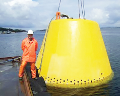
The first SWIT pilot system was deployed in July 2009, Fig. 4. The prototype, which contained a still room structure, an electrochlorinator, a hydroxyl radical generator and control equipment, was designed to process 7,500–15,000 bpd of seawater for injection.
 |
|
Fig. 4. The first SWIT unit was deployed in July 2009. It could handle 7,500–15,000 bpd of seawater. It contained a still room structure, an electrochlorinator, a hydroxyl radical generator and control equipment, all covered with a trawler cage.
|
|
The new technology produces high-quality injection water without requiring water flowlines from the topsides to the subsea wells, which has the potential to save a lot of money, especially in deepwater oil fields. It also may provide operators more flexibility in designing waterfloods for their fields and is an easy add-on at any stage of field life.
Lunde said a second, 500,000-bpd pilot plant is being planned.
TOWARD A SUBSEA COMPRESSOR
Under development for a decade, the Siemens Turbo Compressor–Electrical, Canned and Oil-free (STC-ECO) is the Siemens platform for evolving the concept of subsea compression. In 1999, Shell invited Siemens to develop the industry’s first sealless compressor. The prototype compressor, called ECO-II (economic and ecological), was jointly developed by Siemens and Shell and deployed in late 2006 at NAM’s Vires-4 gas field in the Netherlands. It was tested for more than two years in onshore applications with dirty process gas and was subjected to a wide range of contaminants, including sand and water.
Following the completion of field testing, the compressor was rebranded STC-ECO, and it now operates as a standard compressor.
As the next step toward developing the STC-ECO for subsea use, Statoil and Siemens signed an agreement two years ago that covers a testing program to enhance its efficiency and prove its robustness at Statoil’s K-Lab facility, which simulates real subsea process conditions.
“A revolution is needed in rotating equipment,” said Gerrit Lenderink, head of new applications and systems strategy for rotating equipment at Siemens Oil & Gas Solutions, at a recent E&P forum in The Woodlands, Texas. “The goal is subsea compression, and this will take decades. Currently, the mean time between failures is 1.5 years for a typical compressor; 80% of these failures are caused by liquid ingress. An average upstream compressor is subjected to about 50 trips, compared to only four for a typical downstream compressor. We need upset tolerance. We need a major re-think.”
The STC-ECO is a canned centrifugal compressor unit with an integrated, variable-speed electrical motor drive suitable for dirty gas. It has a solid rotor, a canned motor and a single drain. No electrical part comes in contact with process gas, and transformer oil cools the motor stator in a closed loop; thus, there are no gas emissions. Whereas traditional compressors in use today still use oil-lubricated bearings and are equipped with dry gas seals, the sealless STC-ECO compressor uses magnetic bearings. Its vertical unit arrangement facilitates installation, retrieval and drainage, and the unit can withstand a prolonged pressurized standstill. The footprint of the STC-ECO is 40% that of traditional compressors, although it is 10% heavier.
There are 600 leak points on a typical compressor, but only 150 on the STC-ECO because it contains half the number of components and no gear box. Lenderink claimed a five-year maintenance interval even in the presence of dirty gas, which fully complies with API 617 specifications. “I’ve never seen clean gas in upstream,” he said.
Studies show that about one-third of global natural gas resources are sour and acidic. This dirty gas damages compressor seals, resulting in downtime and gas emissions. In fact, seal system failure accounts for as much as 70% of typical compressor downtime, resulting in average maintenance intervals of less than two years, which is unacceptable for subsea use.
“Safety is always No. 1 in our industry, but uptime is No. 2,” Lenderink said. “Reliability has been called ‘the Subsea Grail.’ The weakest link is upstream gas treatment, not the compressor, and the dry gas seal is the weakest link in the dry/wet compressor.” 
|


