Drilling in multiple surface casing strings at Peng Lai Field saved time and money.
Frank Fu, Stephen C. Actis and Kevin Strachan, ConocoPhillips
ConocoPhillips is developing Peng Lai Field in Bohai Bay offshore China with six WellHead Platforms (WHPs) in 28 m (92 ft) of water. Phase I entailed one 24-slot WHP and a leased FPSO, which has been in production since 2002. Phase II will have five 40-slot WHPs and a permanent FPSO. Phase II production began in 2007.
The 24 inner slots of four of the Phase II WHPs will have 20-in. drive pipe conductors, and the 133⁄8-in. surface casing will be installed by casing drilling. The 16 outer slots, eight on the north row and eight on the south row, will have 36-in. drive pipe conductors and provide dual-bore 133⁄8-in. surface casing strings in each slot. These holes will be directionally drilled at a slight angle to facilitate subsequent directional drilling. The 56 wells, drilled from a 40-slot WHP, reduce the size and cost of the platform, while providing additional wells to meet the reservoir development plan.
This article describes the well construction program as part of the field development plan, the installation procedures, results of the surface casing installation programs and the drilling cost savings realized by using casing drilling and dual-bore conductor technologies.
PENG LAI FIELD
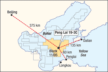
Peng Lai Field was discovered in 1999 in Bohai Bay, China, Fig. 1. Phase I drilling and completion operations began in April 2002 on one 24-slot WHP. Planning for Phase II included extensive studies by multidisciplinary teams. Combining Phase I lessons learned and the drilling and completion best practices to meet the subsurface development plan resulted in a well construction plan and methodology optimized for Phase II development.
 |
|
Fig. 1. Peng Lai 19-3 Field was discovered in 1999 in Bohai Bay, China. Phase II will have 228 wells.
|
|
That drilling is being conducted on five 40-slot WHPs using a jackup and five drilling, completion and workover rigs. Phase II will have 228 wells: 162 producers, 54 water injectors, seven appraisals and five Cutting Re-Injection (CRI) wells. There will be one CRI well on each WHP.
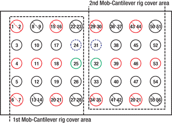
Conductors. The 40 conductors are spaced out at 2.27 m x 1.9 m center to center, Fig. 2. They (20-in. or 36-in.) are driven to 52 m below the mudline (120 m below the rotary table) after the installation of the WHP jacket. There are sixteen 36-in.-diameter and twenty-four 20-in.-diameter conductors on WHPs B, C, D and E, with forty 20-in. diameter conductors on WHP F. Conductor sharing technology in the two outermost rows of slots (eight on the north row and eight on the south row) on the B, C, D and E platforms allows 56 wells from the 40-slot platforms.
 |
|
Fig. 2. A 40-slot surface layout combined with conductor
sharing allows 56 wells to be drilled. Wells include cutting
re-injection candidate wells (green), cellar deck wells (red) and mezzanine deck wells (black).
|
|
Surface casing. The 133⁄8-in. surface casing strings, using both casing drilling and dual-bore methods, are installed during batch setting programs on each platform. The 133⁄8-in. surface casing is set at 235–247 m directionally to reduce directional drilling times in the 12¼-in. hole sections. The casing specifications are 68 lb, K55, BTC, Range II.
Decks. The wellheads are staggered on the cellar and mezzanine decks to provide improved ingress and egress in the well bay area for wellhead maintenance and emergencies. Unitized wellheads and horizontal trees are used to minimize rig time, allow installation of the flowlines while drilling and ensure reliability. The jackup’s cantilever can access one-half of the well slots from each side of the platform.
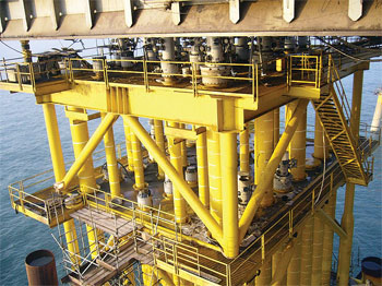
The cellar deck is 20 m above Mean Sea Level (MSL), and the mezzanine deck is 27 m above MSL. The jacket is fitted with a drill deck to allow access to the conductor tops for wellhead installation and drilling operations from the jackup, Fig. 3. The topsides decks are installed over the wellhead decks after the pre-drilling program from the jackup is finished.
 |
|
Fig. 3. The jacket is fitted with a drill deck for access to the conductor tops for wellhead installation and drilling operations from the jackup.
|
|
The installation of the surface casing in the first slot on each platform is done with a diverter to ensure no shallow hazards are present, using either slot 24 or 31, which do not have a hole cut in the conductor. The remaining surface hole sections are drilled and cemented with returns to a hole cut in the conductors at 9 m above MSL.
INSTALLATION IN 20-IN. CONDUCTORS
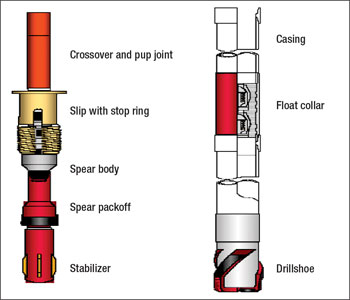
Using Weatherford’s Drilling with Casing technology, 13 3⁄8-in. surface casing was installed through the 20-in. conductors in 24 slots on WHP-C, 24 slots on WHP-B and four slots on WHP-D. A 16-in. drillshoe and a float collar are installed on each end of a full joint of 133⁄8-in. casing onshore. The shoe track assemblies were inspected and shipped offshore for the batch setting operations. The casing drilling assembly was picked up and made up to the top drive system prior to each batch setting program, Fig. 4.
 |
|
Fig. 4. A 16-in. drillshoe and a float collar are installed on each end of a full joint of 13 3⁄8-in. casing onshore.
|
|
DRILLING PROCEDURE
The drilling parameters used during the 13 3⁄8-in. casing drilling operation are 2,000–5,000 lb (0.9–2.3 metric tons) WOB, 60–80 rpm and 500 gpm flowrate to drill in the first two joints below the conductor casing to minimize washouts. The drilling parameters are increased to 2,000–20,000 lb (0.9–9.1 mt) WOB, 60–110 rpm and 900-1,100 gpm pump rate until the casing point is reached. The hole section is drilled with seawater, and high-viscosity sweeps are used as required for cuttings removal. The 16-in. hole is drilled through the 20-in. drive pipe. A 20-in. wellhead is installed on the conductor prior to running 133⁄8-in. casing.
The casing is cemented with 12.5-ppg cement slurry, taking full returns through the hole cut in the conductor at the 9-m level. Limiting the returns to the 9-m level ensures full returns and facilitates subsequent top jobs to cement up to the wellhead level. Gyro directional surveys are obtained on wireline offline after the rig is moved to the subsequent well operation.
When drilling with casing, the stiffness of the 133⁄8-in. casing resulted in the wellpath following the same course as the 20-in. drive pipe azimuth and inclination. Therefore, it was critical that the 20-in. conductors were driven as vertically as possible. The 48 surface casing strings on WHP-C and WHP-B, installed with the casing drilling method, were trouble free. However, the 20-in. conductors driven on WHP-D were found to have some inclination, allowing only four of the first 12 surface casing strings to be installed using this method. The other eight slots required conventional drilling methods.
Two of the 13 3⁄8-in. casing strings installed with casing drilling on WHP-D were directionally drilled using a nudge drillshoe with jets installed preferentially in one direction. The casing was scribed, and angle was successfully built in the desired azimuth as planned.
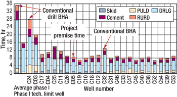
The average time to install one 133⁄8-in. casing string is 8.3 hr (from rig skid-in to rig skid-out) on WHP B and WHP C. The cost savings realized by using casing drilling are about $3.5 million per platform, as compared with cost estimates using conventional drilling. The time saved allows more pre-drilled wells per platform, accelerating production.
Figure 5 shows the operational times for the WHP-C surface casing installation. Wells are shown in the sequence that they were drilled. The first two bars reflect the average conventional installation time and the technical limit time for wells drilled during Phase I. Well C24 was drilled with a diverter and a conventional BHA. The Phase II project premise for surface casing installation with casing drilling was 12 hr/well, rig skid to rig skid.
 |
|
Fig. 5. Operational times for the WHP-C surface casing installation show the improvement with casing drilling.
|
|
INSTALLATION IN DUAL-BORE CONDUCTORS
The first step of the dual-bore procedure is to clean out the 36-in. drive pipe with a BHA using a 32-in. stabilizer. The next step is to drill a directional 16-in. hole, building 5–10° inclination using a BHA with MWD tools and a motor assembly. The final step is to open the 16-in. hole to 32-in. using a BHA that includes a bull nose, a 26-in. hole opener and a 32-in. stabilizer with cutting material on the leading edges. The 16-in. hole must be opened with sufficient WOB to prevent hole angle loss during the hole opening process.
Typical of successful batch setting operations, the three BHAs are made up and racked in the derrick before the eight-slot, dual-bore program begins. The three BHAs are then used for each slot and only laid down at the end of the batch program. The dual-bore starterhead is installed on the 36-in. conductor after drilling the dual borehole and prior to running the 133⁄8-in. casing strings.
CASING PROGRAM
To successfully run two strings of 13 3⁄8-in. BTC casings in the dual-bore well, it is necessary to run the short string first, which terminates at the bottom of the opened 32-in. hole section. The long string is then run into the 16-in. rat hole. The 13 3⁄8-in. short string casing hanger is run on drill pipe and landed in the dual-bore starterhead. The long string is equipped with a float shoe, one casing joint and a float collar. The short string is equipped with a guide shoe only. The coupling on each joint has been beveled on both ends to 45° to ensure that the couplings will not hang up. Only the outer 2⁄3 in. of the shoulder of the coupling is beveled.
CEMENTING
A conventional cement head is made up to the long string, through which the cement is pumped into the dual-bore well and displaced with a wiper plug and seawater. A swedge with a 4-in. ball valve is made up to the short string. When cement returns are observed at the return port in the conductor casing at the 9-m level, the ball valve on the short string is opened to allow cement to U-tube from the annulus into the short string a pre-determined volume to provide a 15-m “shoe track” length of cement in the short string.
Offline cementing was considered for the 133⁄8-in. surface casing strings, but was not implemented because the time savings were fairly small. Simultaneous activities would have required additional personnel on board, and the added risk and complexity ran contrary to the desire to keep the operation as simple as possible.
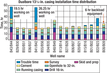
The average time to install two casing strings in a dual-bore well from rig skid-in to rig skid-out is 23 hr on WHP-C and WHP-B. The savings realized using dual-bore wells are about $5.5 million per platform, when compared with conventional drilling and casing. The time saved also allows more pre-drilled wells per platform, accelerating production, Fig. 6.
 |
|
Fig. 6. Dual-bore operational times on WHP-B realized savings of about $5.5 million per platform, when compared with conventional drilling and casing.
|
|
The cement top jobs are performed in the twelve 20-in. and eight 36-in. conductor slots after the batch program is finished on each half of each platform. In the conductor, the 13 3⁄8-in. casing annuli are filled with cement up to the wellhead level once the return ports are welded over and painted.
Similar to the casing-drilled well slots, gyro directional surveys are obtained in both the long string and short string offline after the rig is moved to the subsequent well operation. It was important to obtain the directional surveys as soon as possible after the casing was installed to optimize well trajectories and minimize wellbore collision risk.
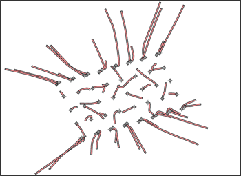
Figure 7 shows the spider plot of the fifty-six 133⁄8-in. casing strings installed at WHP-B. The plot shows the typical directional installation of the dual-bore casing strings, as well as the random azimuth and inclination of the 133⁄8-in. casing strings that were installed with the casing drilling procedure. This resulted from deviation of the driven conductors.
 |
|
Fig. 7. A spider plot of the 133⁄8-in. casings on WHP-B shows directional installation of dual-bore casing strings, as well as random azimuth and inclination, resulting from deviation of the driven conductors.million per platform, when compared with conventional drilling and casing.
|
|
CONCLUSIONS
Installation of the 13 3⁄8-in. surface casing strings was done safely and efficiently using casing drilling and dual-bore procedures in batch programs at Peng Lai Field in Bohai Bay, China. The batch programs were conducted with no recordable incidents.
The verticality of the driven conductor casing is critical to allow the 13 3⁄8-in. casing strings to be installed using the casing drilling method. The hole opening BHA with a bull nose, a 24-in. hole opener and a 32-in. stabilizer performed very well. Wellbore angle can be built with the casing drilling method using a nudge bit.
Cementing of all 13 3⁄8-in. surface casing strings was successful. Online cementing proved to be safe and efficient, so the offline operations were not necessary. The return port in the conductor casing ensures good primary cement jobs and facilitates the cement top jobs.
Gyro directional surveys were obtained on wireline offline as a simultaneous activity. Timely surveys allowed planning of subsequent directional wells in a timely manner.
Batch setting operations provided well construction in a factory mode. The crews perform repetitive tasks that, combined with pre-planning and continuous improvements, refine operational efficiency nearly to the technical limits posed by logistics and equipment constraints. The 13 3⁄8-in. surface casing installation process is at the present technical and logistical limits.
Lastly, lower platform fabrication and installation costs result from the 56 wells that can be drilled from a 40-slot platform, creating estimated savings of $3.5 million per platform compared with cost estimates using conventional drilling. 
ACKNOWLEDGMENTS
The authors thank ConocoPhillips China Inc. and the China National Offshore Oil Corp. for permission to publish, as well as the offshore and onshore personnel who contributed to the safe and efficient installation of the surface casing at Peng Lai Field. This article was prepared from IADC/SPE 112608, which was presented at the IADC/SPE Drilling Conference held in Orlando, Fla., March 4–6, 2008.
|
THE AUTHORS
|
 |
Frank Fu earned a BS in geology from Shanxi Mining College. Fu joined Phillips Petroleum Co., now ConocoPhillips, in 1995. He has 16 years of experience at various positions in drilling engineering, drilling operations, project coordination and geology, including an oversea assignment. Presently, he is the Lead Drilling Engineer working on the ConocoPhillips China Penglai offshore oil development project. Fu is a Senior Drilling Engineer with ConocoPhillips China Ltd. in Beijing, China.
|
|
 |
Steve Actis earned a petroleum engineering degree from the Colorado School of Mines. He has been with ConocoPhillips for 21 years working on major projects in the North Sea and the deepwater Gulf of Mexico. Previously, he worked with Sonat Offshore Drilling in various locations worldwide. Actis is the Chief Drilling Engineer for ConocoPhillips China in Beijing.
|
|
 |
Kevin Strachan earned a BS in mechanical engineering from the South Dakota School of Mines & Technology. He has 27 years of industry experience at various international locations, primarily in drilling operations and major drilling development projects. Presently, he is seconded to Sarawak Shell Berhad as a Drilling Operations Engineer, working on the Gumusut-Kakap deepwater development project offshore Sabah, Malaysia. Strachan is a Senior Drilling Engineer with ConocoPhillips Sabah Ltd. in Miri, Malaysia.
|
|
| |
|


