Paolo Minola and Sara Garavaglia, Saipem SpA, Italy
Tubulars in oil and gas production facilities, offshore facilities, refineries and other industrial settings are subject to impulsive dynamic forces such as water hammer, seismic phenomena and other impact forces deriving from unpredictable handling or anomalous process conditions.
The solution traditionally employed to counterbalance these axial dynamic forces consists of an axially rigid damper or “axial stop,” the purpose of which is to rigidly stop movements. However, this method can discharge unbalanced dynamic forces directly onto the connected structures, and the limited stress transfer time and extreme rigidity of the support structure can amplify those forces.
A new damping system composed of elastic and elastomeric components reduces the strength of impulse-type forces and damps dynamic transitions, allowing the use of lighter load support structures.
COMPONENTS AND FUNCTIONING
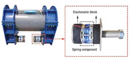
The basic element of the damping system, called SlugStop, is a module consisting of a patented variable-load spring component positioned in series with a pair of elastomeric blocks, Fig. 1. Before installation, the spring component is pre-loaded to several tons so that after the removal of the blocking pins, the resultant force on the structure is zero and the whole damping module is compressed.
 |
|
Fig. 1. The damping system with detail of the spring component and elastomeric blocks that make up the damping module.
|
|
The clamps positioned on the pipe and connected by the tie-rods maintain circumferential contact with the steel pipe by grip and friction. The load, absorbed by the clamp at one side (depending on the direction of the pressure wave) is transferred to the damping module, which transfers a reduced and damped impact force value to the existing structure.
A considerable functional and economic advantage of the new damping system is its high standardization, making it highly modular and adaptable. Each unit is designed to counterbalance a maximum load of 30 metric tons; positioned in series, multiple units of the system can cover a broad spectrum of dynamic problems within a wide range of loads. In this way, loads are redistributed to more than one structure, allowing site managers to avoid expensive modifications and reinforcements of beams and foundations. Transport and on-site handling are also facilitated by the modular nature and easy assembly of the individual units.
The system’s welding-free assembly allows on-site adjustment to the existing structure, even in cases where that structure is different from the design. Examples of this scenario are when the spacing between anchor girders foreseen in the design is different from that actually used on site, and when the thickness of the anchoring foundation designed for differs from that actually built.
FIELD APPLICATION
The first installation of the new damping system was executed at the Dolphin project’s gas-liquefying plant in Ras Laffan, Qatar, in June 2007. The installation was carried out on a 32-in. line subjected to severe conditions of water hammer; analyses performed on the original configuration with traditional rigid supports showed the presence of excessive thrust forces.
A total of 98 units were installed on the whole line length, covering four parts of the plant: the sleeper, the tank farm, the lee breakwater and the berth. The units were positioned both on the axial length of the piping and on the loops, with the compound purpose of reducing and damping the forces and preventing the line from falling from its original side.
BEHAVIOR MONITORING
A field survey was conducted in April 2008 on the Qatar plant to monitor the behavior of the piping in actual pipe hammer conditions. The phenomenon occurred regularly due to recurrent maneuvers during loading of tanker ships.
Two surveys were conducted: a dynamic survey of the line and structure (bridge) during the induced dynamic event, by the application of accelerometers in defined points, and a survey of the maximum relative displacements between the pipe and structures, by the use of appropriate mechanical meters.
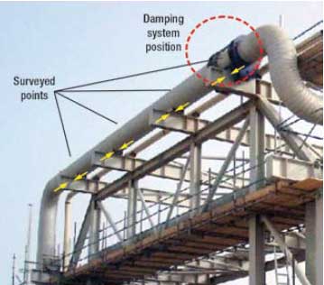
The accelerometers measured the behavior in the longitudinal direction of the line portion where the new damping system was installed, Fig. 2.
 |
|
Fig. 2. Positions of the accelerometers and damping system.
|
|
For the measurements of the maximum displacements of the structures, special mechanical meters were positioned at the positions of the damping system, the lateral guides and the trunnion.
The results obtained with the accelerometers confirm that the impact forces affect the vibration measurements because they produce high-frequency oscillations (noise). The frequency range of oscillation for the structure is 4–6 Hz, while the noise introduced by hitting can reach 200 Hz; as a consequence, the high-frequency oscillations do not influence structure movements.
The survey of displacement detected a uniform movement in the longitudinal direction with a maximum value of 12 mm. The survey showed that the passage of the disturbance had both a direct and indirect effect. The damping system was subjected to a dynamic force that was discharged onto the anchor structure; the movement of the anchored piping, which remained perfectly in line with its original axis, was cancelled when the phenomenon ceased returning to its original position. The amount of damping also proved to be perfectly in line with expectations. On observation, the conditions of the pipe and structures proved that they were intact and functioning.
After a year of operation, operator Dolphin Energy reported satisfactory performance of the damping system.
FUTURE APPLICATIONS
A second successful installation of the damping system was executed on a piping system at the base of the stack of a high-pressure flares in the third train of the Ruwais natural gas liquids plant in Abu Dhabi, UAE.
An upcoming application is planned for a fiberglass piping system at an ammonia-urea plant to protect the line and the structures from excessive dynamic forces due to pump trips or power failures associated with water hammer effects.
Another application under consideration is in a 36-in. line of a water injection facility where use of rigid axial stops for damping has resulted in water hammer effects that seriously compromised the structural supports. 
|
THE AUTHORS
|
| |
Paolo Minola is the Coordinator of a technical department of Saipem working in Milan and San Donato, Italy. His work is mainly focused on the conceptual development of innovative mechanical components for petrochemical plants. Mr. Minola earned a degree in structural engineering at the Politecnico di Milano University in Italy. He is the author of a number of books in the field of construction and the inventor of several patented mechanical components.
|
|
| |
Sara Garavaglia operates in a technical department of Saipem in Milan and San Donato, Italy. Her work concerns the mechanical design and testing of components for petrochemical plants. Ms. Garavaglia earned a degree in structural engineering at the Politecnico di Milano University in Italy.
|
|
| |
|


