As these types of surveys become more common, their inherent acquisition complexity means that repeating source positions, especially for 4D uses, requires special attention.
Damian A. Hite and Philip M. Fontana, CGGVeritas; Bill Slopey and Ian Threadgold, BP
Wide-AZimuth (WAZ) marine streamer survey designs are aimed at increasing the crossline offset and azimuth distributions in marine streamer surveys to better image complex geologies and the sub-salt. Since there is a limited amount of crossline offset that can be achieved with a conventional narrow-azimuth towed streamer spread, most WAZ survey designs have aimed at decoupling sources and receivers, placing the sources laterally from the receiver spread to achieve the additional offset.
Successive passes down the same source lines are then required to extend the offsets. This leads to the familiar concept of a 4D acquisition, where the primary (and most realistic) goal is to achieve a repeat position of the Center Of Source (COS). As WAZ-type acquisitions can require multiple sail-line passes to achieve the required crossline offset, and most require a shot regularization to a fixed grid, it becomes increasingly important to minimize errors in source positioning.1
This article focuses on the navigation requirements for repeat source positioning. It presents recommendations for minimizing the total positioning error based on two acquisitions that represent the before and after application of the recommendations.
INTRODUCTION
Two WAZ surveys were acquired in adjacent blocks in Green Canyon, Gulf of Mexico, using identical source and streamer configurations. The first acquisition occurred in late 2004 to early 2005, while the second acquisition occurred in late 2006 to early 2007. While the configurations of the towed gear remained the same, a number of changes were implemented to the Integrated Navigation Systems (INS) on the vessels to improve the accuracy of the source positioning. Changes in INS over the two programs are shown in Table 1. Before the results of the INS changes are presented, we must first look at where errors in source position originate.
| TABLE 1. INS differences from Season 1 to Season 2. |
 |
|
POSITIONAL ERROR ORIGINS
Errors in source positioning come from four places:
1. Error inherent to the DGPS systems-these errors are relatively equal among all seismic contractors since they are all subject to the same providers of correction information.
2. Positioning of the source array-these errors are related to the quality of the observations returned from each of the sub-array elements to calculate the COS. These are typically GPS and acoustic observations.
3. Shot prediction-this is the predicted shot location relative to the actual source array location. In the best-case scenario, each source vessel predicts its own shot positions, which means that each vessel can acquire shots that are calculated without a layback. For dual sources, a steered point between the two arrays must be chosen. This can allow greater errors when currents cause the guns to skew. If a single source is used, the center of that source is used for the positioning of shots and, thus, gun skew is eliminated.
4. Steering of the vessels-in most cases, the crossline is controlled by the INS, so the errors there are marginal, especially with single sources. The inline is a function of the operators of the vessels themselves being able to govern the speed of the vessel to hit the desired shot location at the right time. If each vessel has its own shot prediction, variations in the speeds of the source vessels become less critical, as a vessel can shoot any time it hits the shotpoint location, provided it is within the record dead time between shotpoints.
TERMINOLOGY
It’s probably good to take a brief moment to discuss the terms used above, in particular, layback. More than a few people are not familiar with laybacks as a source of large errors. As geophysicists, we often spend a lot of time worrying about seismic data, and those of us who do delve into the navigation side of things are often more concerned with the processing methods used to get the final positions for the nav-merge than we are about the actual settings used to configure the systems. All too often, the authors have seen that setup errors, or more commonly, misunderstanding what a system setting actual does, can make the difference between an accurate position and a poor one.
Layback, in this article, is defined as an offset that is projected along a constant heading from a predicted position. In this case, no observations can be made to, or from, the offset location that would allow a more accurate position to be calculated. Over large distances, errors that result from currents become more pronounced.
The closest principal to this in nautical terms would be “dead reckoning,” which is discussed in The American Practical Navigator, first published by Nathaniel Bowditch in 1802. This tome is considered by some to be the epitome of navigation technique as testified by the many subsequent editions. The authors highly recommend a perusal of the material, particularly Chapters 7 and 21−23, which are dedicated to dead reckoning, calculations and error determination.
LAYBACK ERRORS
The effect of laybacks that result from shot prediction must be considered carefully, since this is undoubtedly the largest source of system errors. Laybacks by nature have a rotational error associated with them that increases as the layback increases and is mostly represented in the crossline component. Figure 1 shows the error associated with an angle (w) and a layback (r) from the vessel reference point. If, for example, a 10° feathering angle was observed and the layback from the vessel reference was 150 m, then the inline error would be 2.3 m and the crossline error would be 26.0 m.
 |
|
Fig. 1. Errors associated with laybacks.
|
|
Carrying on with this concept, there is an additional cumulative error associated with skew in the array geometry (Fig. 2) caused by the same feathering angle. Figure 3 illustrates the way these would be viewed by an observer on the survey vessel for a vessel steered by layback and a vessel steered by the center of the source arrays, in both a low-dynamic and high-dynamic environment. If we were to remove the layback, the crossline error would decrease to 5.4 m, and if we were to then remove the gun skew (by going to single source), the crossline error would decrease to sub-meter.
 |
|
Fig. 2. Errors associated with gun skew for a dual array setup.
|
|
 |
|
Fig. 3. Source positioning with a) shotpoint layback in low current; b) shotpoint layback in high current; c) no shotpoint layback in low current and d) no shotpoint layback in high current.
|
|
Inline errors can be managed provided all source vessels are predicting their own shots. This affords them the time from the end of the record length until the start of the next record to compensate for any speed differentials that may have occurred. If the shot prediction was tied to another vessel, such as the streamer vessel, then the sources would have to maintain that vessel’s speed, or risk firing whether or not they were at the prescribed location. Since the rear vessel did not create its own shot predictions, it was tied to the lead vessel’s prediction. If the lead vessel traveled a full shotpoint distance, a shot would be fired regardless of its position relative to the bullseye, Fig. 4.
 |
|
Fig. 4. Shot time buffer in the shot line direction.
|
|
LINE DEVIATION AND OUTLIERS
Obstructions in surveys are becoming increasingly common and include tanker ships, drill ships, buoys, ROV vessels, supply vessels, fishing vessels and fixed platforms. Analyzing the data proved to be less than straightforward due to these numerous obstructions, which subsequently caused source vessels to deviate from the pre-plot line. Furthermore, since the sensitivity of source positioning as relates to the processing sequence is relatively unknown, the source vessels acquired shots throughout the deviation. These data were processed; therefore, these outliers were included in the initial data set.
In addition to the deviations caused by obstructions, in Season 2, the source vessels acquired data in the turns, which produced large-scale deviations from the pre-plot shot position even though it provided usable data with a large degree of azimuthal variation.
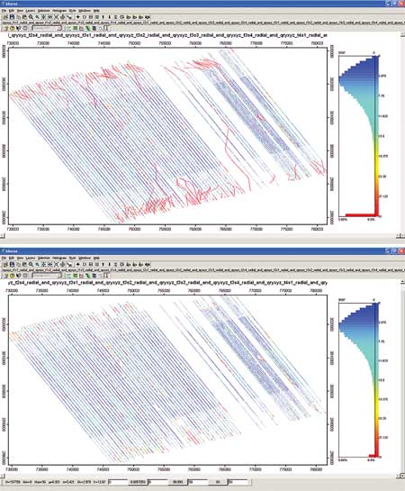
It was clear at this point that all these deviations would be problematic for any statistical analysis, so a method of aerial plotting and filtering was chosen to remove the outliers and visually QC the results. Figure 5 shows the effects of the filtering process.
 |
|
Fig. 5. Before and after outlier removal.
|
|
RESULTS
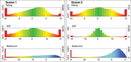
Figure 6 shows the errors between the INS systems used in Seasons 1 and 2 in the along line, crossline and radial components. Of most interest is the fact that the largest improvements are in the crossline. This is due to the fact that the crossline error is most impacted by changes in feather when the vessel reference is used as the shot prediction location, and a layback is assigned to the center of source. The along-line errors are similar between the two acquisitions. At first, this seems a bit contradictory, considering the shot-time buffer arrangement; however, the required efforts of the operators were significantly reduced while maintaining similar accuracies. This could prove very valuable in surveys with long survey lines. In all, the error between the two surveys, represented by the cumulative percentage of radial errors (Fig. 7), indicates nearly a 40% increase in accuracy for errors less than 10 m.
 |
|
Fig. 6. Comparison of positional errors by system.
|
|
 |
|
Fig. 7. Running percentage of radial error.
|
|
CONCLUSIONS
Achieving optimal source repeatability in a WAZ survey requires the following capabilities of the INS:
- Shot prediction-each source vessel should be able to predict its own shotpoints.
- No laybacks--this should eliminate the majority of errors in dynamic situations.
- Timeout shots-the ability to use the record dead time between shotpoints will minimize errors caused by speed differentials in the other vessels in the spread.
Furthermore, it is recommended that, provided the shot density requirement can be maintained, a single source configuration be favored over a dual source configuration. 
ACKNOWLEDGEMENTS
CGGVeritas thanks BP for releasing the data from the two surveys, Michael Shirley and Gary Winfield of the CGGVeritas ATG group for their insight into the INS systems, and John Grant of Concept Systems Ltd. for bringing expectation to reality.
LITERATURE CITED
1 Threadgold, I. M., Zembeck-England, K., Aas, P. G., Fontana, P. M. and W. E. Boone, “Implementing a wide-azimuth towed streamer field trial: The what, why and mostly how of WATS in southern Green Canyon,” Expanded Abstracts, SEG Annual Meeting 2006.
|
THE AUTHORS
|
|
|
Damian A. Hite joined Veritas DGC after earning a BSc with honors in ocean engineering from Florida Institute of Technology in 1997. Previously, he worked as Project Geophysicist Supervisor and Quality Control Geophysicist, with extensive experience with marine survey acquisition and data quality issues in eastern Canada, the Gulf of Mexico, Nigeria, the North Sea, Brazil, Trinidad, Malaysia and Western Australia. He is currently the North and South Regional Geosciences Manager for Marine Acquisition at CGGVeritas. He is a Texas Board of Professional Geoscientists-licensed geophysicist.
|
|
| |
Philip Fontana is the Geophysical Manager for the Marine Acquisition Division of Veritas DGC and, now, CGGVeritas. From 1978 until 1984, he was employed by Ocean Surveys Inc., managing high-resolution geophysical, oceanographic and hydrographic. Between 1984 and 2000, he worked for Western Geophysical in various roles. He also served as Chief Geophysicist for WesternGeco’s North and South America business unit. From 1998 until 2006, he co-instructed the SEG continuing education course, Planning and Executing Marine 3D Seismic Surveys. He has served as a technical advisor to industry groups dealing with marine mammals and seismic surveys. He earned a BS in geology and an MS in geophysics from the University of Connecticut and is an active member of SEG, EAGE and ASA.
|
|
| |
Bill Slopey is a Geophysicist with BP America. He earned an MSc from Texas Tech University in 1986, and is an active member of SEG.
|
|
| |
Ian M. Threadgold is the geophysical ops HSSE network leader for BP Exploration Operating Co. Before joining BP, he worked for Superior Oil Co. until 1978; and before that, he was at Petty Ray Geophysical. He is an active member of EAGE and SEG.
|
|
|


