Drill-and-stress fluid concept builds integrity continously, without interrupting drilling operations.
Fred E. Dupriest, Marty V. Smith and Sabine C. Zeilinger, ExxonMobil Development Company; and Nissan I. Shoykhet, ExxonMobil Upstream Research Company
This article describes a fluid system developed to build integrity continuously to prevent lost returns while drilling. The primary attributes of the fluid that enable this are high solids content and extremely high filtration rates, as reflected in API fluid loss tests. It is referred to here as a Drill and Stress Fluid (DSF).
In field applications, DSF water-based systems appear to be effective over a wide range of conditions. Circulating pressures have been sustained that exceed integrity by 1.0 to 3.0 ppg without detectable losses in depleted formations with permeability ranging from 1 to 1,000 mD and pay zones of 50-700 ft (15-250 m) in length. The mechanism through which the DSF is believed to arrest the growth of lost returns fractures and build near-wellbore stress is described. Generalized design criteria for a DSF system are presented, and the assumed relationship between the design parameters and fluid performance is discussed.
The results of the application of DSF are presented for eight wells, including post-treatment evaluation logs of the drilling-induced fractures created while building stress. Operational practices that facilitate the safe use of an extremely high-fluid-loss system with overbalance exceeding 2,000 psi are also discussed.
INTRODUCTION
In the mid-1990s, the operator developed a family of practices for managing lost returns that are referred to as the Fracture Closure Stress (FCS) Operational Practices.1 These practices are now applied uniformly worldwide by operator’s affiliates, and the success rate in permeable formations is very high.1 However, the FCS practices are discrete treatments as are the majority of industry concepts. Drilling operations must be interrupted to position a discrete pill at the loss zone, and non-productive rig time accumulates as the operation is performed.
The DSF concept is built on many of the basic principles proven in the development of the discrete FCS practices. However, in the DSF process, the integrity and increase in near-wellbore stress are built continuously through specific attributes of the drilling fluid so that rig time is not lost. The rig time cost savings from continuous treatment is significant.
Even greater costs may be incurred if it is necessary to run a string of casing immediately above a low-integrity formation to prevent underground flow or borehole collapse following lost returns. When losses occur, the BottomHole Pressure (BHP) immediately declines to equal the Fracture Closure Stress (FCS) of the induced lost-returns fracture, which approximately equals the far-field stress. The fracture essentially acts as a pressure relief valve, and it is not possible to elevate the BHP by filling the annulus continuously, regardless of fluid density used. If the FCS in a depleted reservoir is less than the pore pressure in shallower formations, underground flow occurs downward to the loss zone. If the FCS is less than the pressure required to stabilize the exposed shale intervals, the borehole will collapse and the string becomes stuck.
Continuous treatment is also needed if long intervals of low-stress formations must be penetrated and Equivalent Mud Weight (EMW) cannot be cut below the FCS so that losses occur in every increment of new hole drilled. The operator’s discrete practices have been effective in stopping these losses, but they return when drilling resumes and new, low-stress formation is exposed. This is a common issue in high-angle, extended-reach wells due to the long measured depth required to traverse even relatively thin sands.
INTEGRITY AND FRACTURE CLOSURE STRESS
The DSF is designed to address fracture propagation losses, which are the cause of over 90% of the operator’s trouble cost related to lost returns.
A fracture is created when the borehole pressure exceeds the stress holding the rock closed. A small amount of additional pressure may be required to overcome the tensile strength of the rock, but sedimentary formations typically have very little tensile strength. In the majority of formations, integrity simply equals the stress holding the hole closed. In the mid-1990s, the FCS practices were developed on the principle that integrity was increased by widening the lost-returns fracture.
This was initially concluded from the simple linear elastic equations used to predict fracture geometry when designing stimulation treatments. The wider the gap, the greater the compression and resultant closing stress between the fracture faces. A significant portion of this stress is also shown to transfer around the face of the borehole so that opening pressure is increased on all sides. This is believed to be the process through which successful particulate Lost-Circulation Material (LCM) treatments work, rather than simple “plugging.”
For an LCM treatment to be effective, its design and placement technique must achieve two objectives: the tip of the fracture must be isolated from borehole pressure to prevent it from extending, which would prevent the buildup of pressure required to widen the fracture, and the width must be achieved that results in the closing stress (integrity) required to drill ahead. The width and closing stress achieved are eventually trapped by the barite and LCM solids that pack the fracture during the treatment. In 13 years of conducting controlled FCS treatments, the operator has not observed any case where the closing stress has been lost after it was achieved and confirmed. The most significant challenge in this process is isolation of the tip from the pressure that must be built to widen the fracture. Various products, such as LCM, cross-linked polymers and cement, achieve this through different mechanisms, and with varying degrees of effectiveness.
TIP ISOLATION, IMMOBILE MASS AND FRACTURE LENGTH
Discrete LCM treatments achieve tip isolation when the pill loses sufficient filtrate that the solids remaining within the fracture become immobile. Because the solids are no longer fluid, they cannot transmit pressure to extend the tip. The high success rate of the FCS treatments results from specific changes made in pill design and placement techniques to enhance the rate at which the carrier fluid is lost and the immobile mass develops.
In a continuous process, the development of the immobile mass is significantly more challenging to achieve. The primary difference is that the fracture length can be controlled in the discrete placement if the proper operational techniques are used. Control of the fracture length is essential because the level of stress that is achieved for a given width is heavily dependent on the length of the fracture. Figure 1 shows the relationship between length, width and stress increase calculated from a linear finite-element model. This relationship has been widely discussed and modeled by the industry.2 It is generally agreed that if the fracture growth is not arrested quickly so that the length is constrained, a continuous treatment will either fail completely or achieve only small increases in wellbore opening pressure.
 |
|
Fig. 1. Results from finite element model showing relationship between length of propped fracture and width required at the wellbore to achieve a desired increase in stress (integrity).
|
|
The implication for the design of a continuous treatment system that depends on development of an immobile mass is that fluid loss must occur very rapidly. There is also a logical question as to whether the system will be effective in formations with low permeability, low drawdown (differential), or in Non-Aqueous-based Fluids (NAF). The case histories discussed below show that DSF has in fact been successful in permeability of less than 0.01 mD in water-based fluid systems.
The conclusion drawn from the success of DSF in very low permeability is that much of the carrier fluid may escape to the tip, rather than to the matrix of the permeable fracture face. Figure 2 shows a schematic of the assumed process. As solids enter the fracture, the mobility of the carrier fluid is greater than that of the solids due to particle drag at the face of the fracture and effective shear stress between the particles within the fluid. If the carrier fluid has very high mobility relative to the solids, the solids may become concentrated as fluid escapes to the tip. The solids eventually become immobile, though the filtrate continues to pass through to the tip.
 |
|
Fig. 2. DSF design assumes carrier fluid is lost to both the fracture face and the tip. Fluid components are selected to enhance the free flow of filtrate through the solids.
|
|
An unusual feature of the DSF system is that extension of the tip by only filtrate does not greatly reduce the fracture closure stress at the wellbore. The buildup of filtrate pressure will open and extend the tip, but it will only create sufficient width to allow the filtrate to pass, which is quite narrow. It is necessary to distinguish between the propped fracture length with immobile solids and the unpropped fracture length extending beyond the solids. It is not the extension of the tip that causes the stress decline at the wellbore, but creation of width at the tip of the propped length. Whether the tip at the end of the propped length is fully closed or a few microns wide, the geometry of the propped region is essentially the same. This conclusion follows from the fact that the stress at the wellbore is a product of the strain created by the fracture shape, and there is very little difference in propped shape if the extended tip is very narrow. In contrast, if the solids do not become immobile, the particles themselves press against the tip. If fluid loss control exists, differential pressure may build against the lead particles so they drive the width to a dimension that will accept the particles. This width may range from that of larger barite (100 microns) to the LCM in the fluid (commonly 400 to 1,000 microns). The change in shape of the propped fracture and strain are significant and the stress at the wellbore declines.
Figure 3 shows a comparison of the modeled FCS for the two cases. In the first case, the propped length is 1 ft and the width at this point is assumed to be 10 microns. In the second, the width at 1 ft is assumed to be 400 microns. In both cases, the tip is being extended so the pressure within the fracture is modeled as the minimum formation stress. Significant stress can still be achieved in the fracture having a width of 10 microns at 1 ft, which simulates the effect of filtrate alone opening the tip. The fracture having 400 microns of width, which simulates tip propagation with mobile LCM, achieves 850 psi less closing stress in a fracture with a width of 500 microns at the wellbore. The modeling suggests that it is not necessary to isolate the tip from borehole pressure to achieve the desired FCS; it is only necessary to create the desired propped geometry.
 |
|
Fig. 3. Comparison of stress at the wellbore for a fracture geometry having 10 microns of width at the propped tip versus 400 microns based on finite element analysis models. A constant shear modulus of 1 million psi is assumed.
|
|
DSF DESIGN
The DSF system is designed to maximize fluid loss and the rate at which the immobile mass will develop. Many of the design concepts are built on previous experience with high-fluid-loss, discrete FCS treatments. One significant difference is in selection of particle size. In FCS treatments, LCM with a mean particle size (D50) of approximately 400 microns is used globally in all applications. In the DSF process, the particles must be engineered to create drag within the fracture, so that fluid transmissibility to the tip is higher than that of the solids. This drag has not been required in the FCS treatments because of the placement technique used. A typical design basis for a water-based DSF includes:
- Solids content of 20-40% by volume (including weighting agents)
- API spurt loss greater than 10 to 15 ml (actual typically greater than 30 ml)
- No filtration control material
- Diatomaceous earth greater than 2% by volume
- Attapulgite as the primary suspension agent
- Particle size distribution with 80% less than required fracture width
- Particle size distribution with poor packing efficiency
- Less than 10% particulate material of less than 30 microns
- Fracture design length of 0.5-10 ft, depending on permeability.
MAXIMIZE SOLIDS CONTENT
The high concentration of total solids reduces the fluid loss required to develop an immobile mass. Figure 4 shows that relatively small changes in the starting solids concentration may have a large effect on the amount of fluid loss needed to develop immobility. All examples are for a fluid mixed to have a density of 13.7 ppg with differing amounts of LCM and barite. In the first example the LCM is nut hulls, having a Specific Gravity (SG) of 1.2. In the second example, the LCM is graphite, having a density of 2.1 SG. The first two examples show fluid designs with 30% solids volume (72.7% water volume) and 40% solids volume (62.2% water volume). Although the fluid with lower solids concentration contains only 16% more water, it may be necessary for it to lose 100% more volume to develop into an immobile mass.
 |
|
Fig. 4. Initial solids content is maximized to reduce the fluid loss required to achieve immobile mass. Target total solids content is typically 20-40%.
|
|
The second and third bars in Fig. 4 show that selection of LCM density is also critical because this determines the maximum concentration of LCM that may be placed within a fluid and yet retain pumpability. In this case, if an LCM of moderate 2.1-SG density is used, it is only possible for 28.5% of the total volume to be composed of this material. The remainder must be high-density barite or the total solids content will exceed the assumed 40% design threshold for pumpability. If a higher-density material, such as calcium carbonate (2.6 SG) is used, it is possible for the entire 40% solids-content volume to be LCM. In this manner, LCM is being used as both a lost-circulation material and a weighting agent. Generally, solids content is maximized by using low-density LCM for low-mud-weight applications and high-density LCM for high-mud-weight DSF.
MAXIMIZE SPURT LOSS
The spurt loss using aloxite disks as the filtration medium is used as a relative indicator of fluid transmissibility through the solids. The design objective is to maximize spurt, and field fluids have been designed with spurt losses in excess of 30 ml. A minimum threshold of 10-15 ml appears to be achievable with all carrier fluids. The observed modified High-Temperature, High-Pressure (HTHP) cumulative fluid loss values have been in excess of 200 ml/30 min.
Lab tests have shown small percentages of diatomaceous earth to enhance the fluid loss. Diatoms are microscopic skeletal remains that are irregular in shape and exhibit poor packing efficiency. Figure 5 shows the effect of various concentrations of diatomaceous earth added to a DSF system. Relatively low concentrations appear to be sufficient to disrupt the packing efficiency of the other solids.
 |
|
Fig. 5. Low concentrations of diatomaceous earth significantly enhance fluid loss.
|
|
Attapulgite is the operator’s preferred suspension agent for water-based DSF systems because it does not reduce fluid loss as plate-like bentonite or polymers do.
MINIMIZE PACKING EFFICIENCY
Although the DSF system contains no filtration material (i.e., bentonite, starch, polymers), the solids may resist movement of interstitial water if the particle size distribution allows high packing efficiency. Only four types of solids are used in the DSF design: 1) LCM, 2) diatomaceous earth, 3) attapulgite and 4) weighting agent. The preferred LCM has a narrow particle size distribution and low packing efficiency. The most problematic component is the weighting material. API barite is intentionally ground to a size distribution that packs efficiently. Consequently, barite is not used in the DSF system as a weighting agent if the desired weight can be achieved by varying the density of the LCM.
PARTICLE SIZE AND FRACTURE GEOMETRY
A number of fracture geometry models have been developed to calculate the width that must be sustained in order to achieve a given increase in FCS. However, there is significant uncertainty in the values used in these calculations. A single vertical lost-returns fracture, for example, may pass through a variety of rock lamina with widely varying elasticity. However, a single average value of elasticity is usually used in the calculation of fracture width. As previously shown in Fig. 1, the length at which the growth of the fracture is arrested also has a large effect on the width required to achieve a desired FCS. The combined uncertainty in the fracture width calculation is significant.
Because the DSF system arrests fracture growth through the development of an immobile mass, it is not essential to determine the precise width of the opening. Particles of any size become immobile when sufficient carrier fluid is lost. However, in situations where the primary mechanism for fluid loss is extrusion of the water to the tip, it is still assumed that particle drag along the tapered geometry of the short fracture is desirable. Consequently, the DSF design process includes the calculation of the theoretical width and selection of LCM with a particle size distribution that fits just within the fracture. The objective is not to plug the opening, so ideally 80% of the particles will be selected to fit within the design width.
Sensitivity analysis is conducted on fracture lengths of 0.5 to 10 ft to determine the effect on width. Where high permeability and severe drawdown ensure rapid loss of carrier fluid, the length is assumed to be in the lower end of this range. In very low permeability where development of the immobile mass may be more difficult, the design fracture width is based on lengths in the upper end.
MANAGEMENT OF STUCK-PIPE RISK
The continuous use of a high-filtration rate system (HTHP cumulative fluid loss values greater than 200 ml/30 min.) raises concerns that poor cake quality will result in stuck pipe. The operator has developed a number of practices to reduce this risk, and there has been no indication of sticking or tight hole in the field application of DSF to date.
High fluid loss results in rapid filter cake growth under static conditions. However, the shear strength of the cake is dependent on the differential pressure across the solids that form the cake and the “friction angle” of the solids. In order for differential pressure to develop to apply stress between the solids, there must be some level of fluid loss control. Fluid conductance through the DSF system is sufficiently high that the differential across individual particles is not significant. Consequently, although a loose cake may form under static conditions, it has no strength and stabilizers and bits pull freely through it. When circulation is initiated, fluid shear washes much of the weak cake from the face of the formation.
In field applications to date, a conventional low-fluid-loss mud has been circulated into place at the end of each interval. Caliper logs have shown no significant cake growth in formations with over 2,000 psi of differential. Torque has also been monitored continuously while drilling for indication of stabilizer drag caused by the development of shear strength in the cake, and none has been observed. The ease with which the filter cake growth has been managed was unexpected, given the industry’s long history of stuck pipe in LCM-laden mud. The conclusion drawn is that filter cakes in severely depleted intervals must either be very efficient (thin), or very inefficient (weak and easily removed with mud velocity). It is with intermediate fluid loss rates that cakes develop a combination of both thickness and high internal shear strength, leading to stuck pipe.
Consequently, the primary risk associated with the DSF is that the buildup of fines as drilling progresses will reduce the fluid loss to levels where high cake strength develops. This is a particular concern in uninhibited water-based fluid systems. Though sticking did not occur during field trials, a process was applied to treat the suspect intervals preemptively with discrete, low-fluid-loss pills. These treatments are referred to as Quality Ream and Seal (QRS) treatments. The concept was first developed in the 1990s and was used to condition filter cakes in severely depleted sands. After a stand is drilled down, a 30-bbl, low-fluid-loss QRS pill is circulated around the BHA at the lowest rate practical. As the pill travels up the annulus around the BHA, the string is reciprocated and the stabilizers are rotated to strip the original drill-solids-laden cake in the presence of the QRS pill.
FIELD TRIALS
Results are presented from the application of DSF in four wells in Jerneh Field in Malaysia and four wells in Trawick Field in East Texas. The two programs test extremes in the application of the method. Jerneh formations have Darcy permeability and high drawdown, both of which are favorable to the rapid loss of carrier fluid. In contrast, Trawick is a tight gas reservoir with permeability of less than 0.1 mD where leakoff of the carrier fluid might be quite low. Matrix leakage would be expected to dominate the development of the immobile mass in Jerneh, while it is assumed that significant leakage to the tip would be required in Trawick. The application was largely successful in both extremes.
 |
|
Fig. 6. Common suspension agents, such as xanthan gum, viscosify the water phase and reduce fluid loss. The effect may be particularly pronounced in very low permeability with small pore throats.
|
|
Jerneh Field application. Jerneh Field was Malaysia’s first and largest gas discovery. Reservoir pressures had declined in some intervals to 3 to 4 ppg and the corresponding FCS was expected to be below the original pore pressures in adjacent sands, which would have allowed underground flow following losses. The DSF was used to eliminate losses, to allow the mud weight required for stability to be maintained and to prevent underground flow.
Figure 7 shows the pore pressure and integrity profile for one well. While drilling with DSF, the Equivalent Circulating Density (ECD) exceeded the integrity in three and possibly four zones by 1 to 3 ppg. The performance of the DSF allowed two of the planned casing strings to be eliminated. A third string might have been omitted but it was run as the performance of the DSF during this early application and the potential consequences of underground flow were still undetermined.
 |
|
Fig. 7. ECD exceeded integrity by 1 to 3 ppg in three zones. Prevention of losses allowed two casing strings to be eliminated.
|
|
Three of the four wells were drilled with no losses. The fourth well experienced a single loss incident in Zone B. The well stood full with a static head 1.0 ppg greater than the estimated integrity, but could not be circulated. A discrete FCS treatment was conducted, and drilling continued without additional losses.
The fluid used in the Jerneh program did not have all of the attributes of the DSF as it is defined today, because the particle size was not engineered. The LCM consisted entirely of nut hulls with a D50 of 400 microns, which is standard for the operator’s discrete FCS treatments. Particle size engineering was not introduced until the Trawick program, where extrusion of the water through the particles to the tip was assumed to be essential to the development of the immobile mass in very low permeability. It appears that these favorable conditions, including high permeability and high drawdown, allowed the required immobility to be achieved in Jerneh without the use of engineered particles.
Trawick Field application. Trawick is a tight gas field in East Texas. The Travis Peak is a depleted interval approximately 700 ft thick, extending from 8,100 to 8,800 ft in TVD. The severity of depletion varies across the field, but FCS less than 8.4 ppg has been observed following some losses in the pay zone and loss volumes as high as 7,000 bbl have been experienced in individual wells. Losses have been successfully stopped with discrete FCS treatments, but the length of the loss zone and the need for multiple treatments as new formation is exposed render the process costly and impractical. More significantly, the drop in BHP following losses to FCS values of 8.5 to 9.0 ppg resulted in collapse of low-strength shale exposed above the pay zone. After a number of boreholes were lost, an additional string of casing was added to the standard design at the top of the pay zone. The combination of lost returns and increased casing cost had a significant negative impact on the economics of the tight gas program.
The DSF fluid was used to build stress continuously across the 700-ft pay interval. After the first three wells demonstrated the effectiveness of the DSF, the fourth well was drilled without protective casing. The additional string has now been eliminated from standard designs for the field.
The final Trawick DSF consisted of a water-based system with nut hulls and sufficient calcium carbonate to achieve the desired fluid density of 9.8 ppg. The 200-micron calcium carbonate was used as the weighting agent to eliminate the fines normally contained in API barite. The ECD was approximately 10.3 ppg, and estimated integrity was 9.0 to 9.5 ppg in the specific location. ECD exceeded integrity by 1.3 to 0.8 ppg.
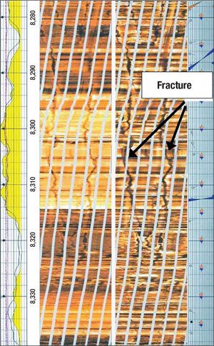
Three minor loss events occurred on the four wells combined. In each case, the volume was less than 20 bbl. Returns were regained without conducting a discrete FCS treatment, and drilling continued. The three events represent a small portion of the pay zone drilled. The fracture identification log confirmed that the ECD had in fact exceeded integrity across most of the pay zone. Of the 700 ft of pay, approximately 400 ft contained similar fractures, Fig. 8. The log showed that even though the ECD exceeded integrity and a fracture was created, the DSF arrested its growth before a detectable volume of fluid was lost.
 |
|
Fig. 8. A short section of fracture identification log run on one well shows fracture initiated by borehole pressure exceeding integrity. Fractures were observed in 400 ft of the 700-ft pay zone.
|
|
WATER-BASED VS. NON-AQUEOUS DSF
To date, the DSF concept has been applied to water-based fluid systems. The development of the immobile mass is expected to be more challenging in NAF. With NAF, higher capillary entry pressures may reduce the fluid loss to the matrix and increased lubricity may limit particle drag within the fracture. Suspension is also challenging since the methods used to suspend solids in NAF also tend to greatly reduce fluid loss.
However, the incentive for developing these systems may be large. Alternative approaches to building stress continuously in NAF depend on rapid bridging at the opening to the fracture, which requires accurate modeling of the geometry and particle size distribution.1 In some cases, it may not be practical to use the large particle size required to achieve this bridging continuously while drilling with conventional equipment in the hole. Because the DSF achieves tip isolation through development of an immobile mass, its success may not be as dependent on particle size.
CONCLUSIONS
A fluid system designed to build integrity continuously to prevent lost returns while drilling has been developed and field trials have been conducted. The DSF behaved like a typical fluid system with good hole cleaning properties and low ECD. Although filter cake growth was not observed, future applications will include fluid processing to more effectively target low gravity solids while retaining LCM so high spurt loss values can be sustained over longer intervals. The Jerneh and Trawick wells were successful in achieving objectives and eliminating casing, and the operator will be testing the DSF in additional fields with chronic lost returns.
Although the field trials have shown the DSF to be effective, they have not necessarily proven the mechanism through which it works. For example, it is not known whether leakage of the carrier fluid to the fracture tip is a major or minor factor in the development of the immobile mass. The success of the DSF in formations of less than 0.1-mD permeability in Trawick suggests that tip leakage may be significant, but this has not been studied under lab conditions where it can be observed and measured. The elasticity of the full-scale field system is difficult to simulate in the lab, as is the significant variability of properties in a laminated interval drilled at angle. Current design practices for particle size and distribution, spurt loss and fracture geometry modeling will be modified based on continued learnings from field data. 
ACKNOWLEDGEMENTS
The authors thank the ExxonMobil Exploration and Production Malaysia Inc. Jerneh drilling team and ExxonMobil Production Company Trawick drilling team for their outstanding work in developing and executing numerous new operational practices that enabled the success of the DSF system. This article was prepared from SPE 112656 presented at the 2008 IADC/SPE Drilling Conference held in Orlando, Florida, March 4-6, 2008.
LITERATURE CITED
1 Dupriest, F. E., “Fracture Closure Stress (FCS) and lost returns practices,” SPE 92192 presented at SPE/IADC Drilling Conference, Amsterdam, Netherlands, Feb. 23-25, 2005.
2 Alberty, M. W. and M. R. McLean, “A physical model for stress cage,” SPE 90493 presented at SPE Annual Technical Conference and Exhibition, Houston, Sept. 26-29, 2004.
|
THE AUTHORS
|
|
|
Fred E. Dupriest earned a BS in mechanical engineering from Texas A&M University. He joined ExxonMobil in 1977 and has worked in a variety of operational assignments. He is currently a Technical Advisor to the global drilling organization in critical well planning, trouble response and performance management. He led the development of ExxonMobil’s fracture closure stress practices to mitigate lost returns, as well as the Fast Drill performance management process.
|
|
|
|
Marty Smith earned a BS in biology/chemistry from Texas A&I University. He joined ExxonMobil in 1978 with assignments as a Rig Supervisor and Well Control Instructor before returning to fluids technology. Smith was a Senior Fluids Specialist focusing on well planning and trouble avoidance before his retirement this year.
|
|
|
|
Sabine Zeilinger holds a Dipl. Ing. in petroleum engineering from the Montanuniversität Leoben, Austria, and a PhD in petroleum engineering from the University of Texas at Austin. She is a technical advisor providing well planning and surveillance support to the global drilling organization in fluids design and narrow-margin drilling.
|
|
| |
Nissan I. Shoykhet holds a BS in mechanical and biomedical engineering and an MS in mechanical engineering from Carnegie Mellon University. He joined ExxonMobil Upstream Research Company in 2005 and performed research on extended-reach drilling, hole cleaning and lost-returns prevention.
|
|
|


