The failsafe, thru-tubing system with a unique wellhead adapter allows chemical injection while maintaining functionality of both downhole and surface safety valves.
Jeff L. Bolding and Steve J. Szymczak, BJ Services; Larry E. Hartman, Chevron; and Brian Erickson, Apache
Liquid loading can slow production in gas wells, and causes many wells to be shut in prematurely. Many artificial lift methods have successfully alleviated liquid loading and allowed the operator to reach the abandonment pressure more quickly, reducing expense. However, most artificial lift methods are not applicable to offshore production due to regulations requiring the use of certain safety systems offshore, in particular a Surface-Controlled Subsurface Safety Valve (SCSSV) and a Surface Safety Valve (SSV). Use of traditional artificial lift methods would impede the operation of these safety devices.
However, BJ Services has developed a failsafe, thru-tubing capillary injection system for offshore wells equipped with an SCSSV and an SSV. Full compliance and functionality of the SCSSV is maintained by using a specialized wireline-retrievable SCSSV. At surface, a unique wellhead adapter allows the SSV to remain functional. These two components are combined with a capillary foamer injection string that allows the well to flow at a lower BottomHole Pressure (BHP), enabling production of additional reserves and improving ultimate recovery.
The capillary injection system, called InjectSafe, was developed for Chevron as part of a larger program to aid production in the many liquid-loaded wells in the company’s Gulf of Mexico assets. The first successful installation was on a pilot well in Chevron’s Vermilion 39 Field, and used an early version of the wellhead adapter called a Y-body. Recently, the thru-tubing capillary injection system was successfully installed in another GOM well for Apache, with an improved wellhead adapter design that overcame several limitations of the Y-body.
BACKGROUND
Artificial lift installation methods typically fall into one of two categories: workover and thru-tubing. Workovers imply that production tubing is pulled from the well. Subsequently, various artificial lift hardware components are installed and the tubing is re-deployed into the well.
Thru-tubing artificial lift systems, as the name implies, can be installed without a workover. Such systems include coiled-tubing velocity strings, plunger lift and capillary strings.
Offshore, however, operational restrictions created by the SCSSV and SSV limit artificial lift options. The methods in the short list above cannot be installed by wireline without crossing the SCSSV and SSV, thus rendering them inoperable. Therefore, they create a unique set of challenges in their application.
Capillary chemical injection. Capillary tubing as a means to deliver chemical to the perforated region of a well is a proven technology for wells that do not have an SCSSV; these are typically land wells. According to data from BJ Services, in North America there are more than 9,500 installations of capillary strings. The typical sizes of capillary strings are ¼-in. and ⅜-in. OD. Typically, the capillary string is inserted into the production tubing from the top of the well through both master valves and is installed as a permanent fixture in the well. Various chemicals can be introduced on a continuous basis via capillary injection. These include foamers, scale inhibitors, corrosion inhibitors, paraffin inhibitors, fresh water, salt inhibitors, gas hydrate inhibitors, demulsifiers and viscosity reducers.
Foamer injection. When applied in the presence of water, foamer reduces the surface tension, facilitating gas entrainment. The gas production creates the agitation necessary for the chemical to create foam. This foam, having a substantially reduced relative density, allows the existing formation pressure to lift it, and thus the liquids, out of the well. In practice, the ratio of foamer to liquid is adjusted until an optimum production level is reached-typically 1-20 gal per 1,000 gal of formation water. There must be sufficient chemical to create the foam but not so much as to have active foam at the surface.
Of the 9,500 capillary installations in North America, 85% are primarily for foamer injection to alleviate liquid loading. Most foamer application recipes incorporate scale and corrosion inhibition packages to treat multiple problems at once. Many wells being completed today would be uneconomic were it not for capillary foamer injection.
SCSSVs. The primary factor preventing capillary use in offshore wells has been the presence of an SCSSV. These valves are designed to stop flow in the event of a catastrophic failure. They are installed in the production tubing and are mandatory in most offshore wells. SCSSVs are held in the open position by positive hydraulic pressure from surface. The hydraulic pressure is transmitted through a control line in the tubing-casing annulus, running from the valve to the surface and exiting the wellhead at the tubing head adapter, where surface controls are applied. If pressure is lost, such as during an emergency shutdown or if the line is cut, the valve will close and revert to its “failsafe” closed position.
Government and industry regulations allow for temporarily obstructing the SCSSV for a thru-tubing application, but the process must be manned around the clock in order to instantly respond to a well control event. There have been cases in which capillary tubing was temporarily installed through an SCSSV to test the viability of a treatment. In those cases, personnel monitored the operation on a 24-hour basis.
SCSSVs are categorized as either tubing retrievable (TRSCSSV) or wireline retrievable (WRSCSSV).
Tubing-retrievable SCSSVs. TRSCSSVs are installed with the production string and are designed to have the same ID drift as the production tubing; thus, their OD is greater than the ID of the production tubing to accommodate the internal moving parts.
TRSCSSVs are regulated under API 14a. In case the TRSCSSV experiences mechanical problems, it can be converted to a hydraulic nipple to receive a secondary insert valve-a WRSCSSV-using the existing hydraulics.
To convert the TRSCSSV to a hydraulic nipple, two wireline steps occur. First, a lock-out tool is deployed and permanently locks open the TRSCSSV. The second step is to deploy a communication tool that penetrates the hydraulic control line in the tubing-casing annulus. Upon completion of these two steps the TRSCSSV is ready to receive a wireline insert valve.
Wireline-retrievable SCSSVs. WRSCSSVs are safety valves built to be deployed and retrieved using wireline, and are often run as backups to TRSCSSVs. Some operators, upon initial completion, choose to install a WRSCSSV landed into a hydraulic nipple, as opposed to deploying a TRSCSSV.
These valves are hydraulically controlled in an identical fashion to that of TRSCSSVs. They consist of a lock to firmly secure the valve in its desired location, external “V” packing or seals that engage a smooth-polish bore to straddle and seal the hydraulic communication port, and a flapper/closure assembly. As noted above, a locked-out and communicated TRSCSSV can serve as the hydraulic nipple to receive a WRSCSSV.
A FAILSAFE CAPILLARY SYSTEM
The thru-tubing chemical feed system for an SCSSV was developed as a cost-efficient method to intervene in older offshore wells. By inserting a modified WRSCSSV into an existing, locked-out TRSCSSV, using the same hydraulics for operation, with capillary tubing suspended below and above the SCSSV, it became possible to initiate a chemical deliquification program. This enables wells to be returned to production using only thru-tubing methods.
The system used in the pilot consisted of three key components: the modified WRSCSSV, a wellhead adapter and capillary tubing with a backpressure check valve attached at the bottom.
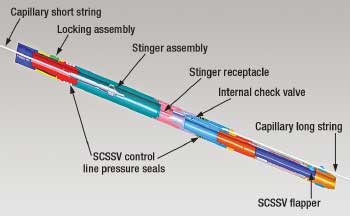
Specialized WRSCSSV. The failsafe capillary system integrates proven capillary techniques with certified SCSSV systems to provide a pathway for capillary injection that bypasses the SCSSV, preserving its full functionality, Fig. 1. The WRSCSSV’s upper extension tube assembly is modified by provision of an internal Polished-Bore Receptacle (PBR) to receive a stinger deployed on capillary. This stinger and capillary form the “short string” of the capillary injection system, from the surface to the WRSCSSV assembly. A series of pathways internal to the WRSCSSV assembly provide communication from the internal PBR to an external capillary connection just above and parallel to the actual valve component. At this location, the “long string” of capillary tubing is attached and suspended from the WRSCSSV assembly to the formation.
 |
|
Fig. 1. Cut-away of the specialized WRSCSSV assembly for capillary injection.
|
|
The installation procedure is as follows:
1. A lockout tool is deployed to permanently lock out the TRSCSSV.
2. A communication tool is deployed to stab through the tubing and hydraulic control line in the tubing-casing annulus above the locked-out TRSCSSV, providing communication to the inside of the tubing.
3. The capillary “long string,” with the check valve at the lower end and the upper end attached to the modified WRSCSSV, is lowered into the hole and through the converted TRSCSSV until the WRSCSSV locks into the converted TRSCSSV. At this point, the location at which the external control line was communicated should be between the two control line pressure seals on the body of the WRSCSSV, restoring full SCSSV function to the well.
4. The stinger is lowered on the capillary “short string” until it locks into the WRSCSSV assembly’s internal PBR.
With this final step, the chemical pathway from the surface to the formation is complete. Both capillary strings are run via a standard capillary injection unit, modified to meet all offshore safety standards and set on a skid for easy transportation. The BHA consists of a dual backpressure check valve, which is adjusted to maintain the hydrostatic column of chemical. In the event that the capillary string were to lose prime or run dry, the dual-check arrangement would aid in preventing flow up the injection line.
WELLHEAD MODIFICATION
The second breakthrough necessary to make offshore capillary injection possible involved the wellhead. Surface Safety Valves (SSVs), also called actuated master valves, are required in the GOM by the US government and operators. Similar to SCSSVs, these valves close as a failsafe when an emergency shutdown is initiated. Also, regulations require the periodic cycling of the SSV, which would cut any capillary tubing run through it. Therefore, the chemical injection capillary needed to be routed so it did not pass through the SSV.
Initial wellhead adapter. The solution deployed in the pilot well for Chevron was called the Y-body. This wellhead adapter integrates a flow cross and the SSV, and negates the typical flange between the two. This raises the center line of the valve, creating additional space to allow the “Y” to intersect the vertical run of the tree at a 15° angle at a point below the upper master. The resulting swap-out of components allows all connections to be re-flanged up without altering the flowline height, Fig. 2.
 |
|
Fig. 2. The Y-body wellhead adapter for capillary injection integrates a flow cross and the SSV and negates the typical flange between the two. The main limitation of the design was that it prevented placement of a backpressure valve needed to maintain to barriers if the SSV or bottom master required maintenance.
|
|
This configuration had several limitations. It took a minimum of four months to manufacture and was expensive, costing around $40,000. It was difficult to clad if necessary, and the Y-extension created additional exposure to potential damage from falling objects. As most items offshore are transported by crane, the latter could pose problems in future applications.
Most importantly, however, since the capillary string passed through the tubing hanger, a backpressure valve could not be placed in the backpressure thread profile if the SSV or bottom master required maintenance. Offshore operators must conduct a quarterly test on the upper-actuated-master valve to confirm that the valve is not leaking. If this valve is leaking, the operator will close the SCSSV and the lower manual master valve to obtain the two barriers required at all times by the US Minerals Management Service (MMS). The job of pulling the bonnet and replacing worn parts can be as quick as 30 minutes.
Assuming that a Y-body with capillary is installed, it is impossible to obtain two barriers to rectify the non-compliance. The operator’s only option will be to pull the capillary string, make repairs and re-install the capillary string. This sobering expense was extremely detrimental to market acceptance of the capillary injection system.
New wellhead system. After the pilot execution, a new wellhead solution was developed with input from Chevron to overcome these limitations. This new configuration, the InjectSafe Wellhead Adapter, consists of:
1. a flange placed between the tubing head adapter and the lower master valve (or tree, in the case of single-block trees)
2. a mandrel
3. a capillary hanger.
The adapter adds 11.25 in. to the height of the wellhead assembly. Upon completed installation of all internal components, an additional backpressure thread profile is provided above the location for chemical injection.
The flange incorporates an inspection port to test seals and a chemical injection port with an integral needle valve. The needle valve closes as an additional protection, along with the downhole check valve, against production through the capillary string.
The mandrel sits inside the flange and engages the flange’s original backpressure threads to provide a primary seal. It has external O-rings to seal against the polished bore of the flange above and below the integral needle valve, providing communication from the chemical injection port to the capillary tubing hanger that locks inside the mandrel, Fig. 3a. The mandrel is designed to be deployed with the same rods and lubricator that are used to introduce a backpressure valve for tree isolation.
 |
|
Fig. 3. In the improved wellhead adapter, a mandrel seals against the inside of the flange and allows communication between the integral needle valve and the capillary tubing hanger, which locks inside the mandrel. The capillary hanger has an integral, kidney-shaped cavity-shown above in cross-section-that allows production flow.
|
|
The capillary hanger is designed to land inside the mandrel and snap into position. The hanger has two seals on the outside that straddle the chemical inlet port, which is accessed through the mandrel. Production flows through a kidney-shaped cavity within the capillary hanger, Fig. 3b. The capillary hanger is landed by a simple running tool.
The advantages of this system over the Y-body are extensive. Manufacturing time for the prototype parts was 4 days, and the finished product cost $24,000. The adapter can be manufactured of any metallurgy and has no external appendages that would invite damage by falling debris. The adapter is directly applicable to single-block trees and to dual-completion trees. Most importantly, all components are below the lower master and the added backpressure threads can be used to obtain a second barrier, allowing full compliance for upper tree work.
Due to its HSE improvements and decreased lead time and cost, this design was used for the thru-tubing capillary injection installation for Apache, and Chevron plans to use it in its future installations of the system.
PILOT INSTALLATION
Due to the high number of liquid-loaded wells in its assets across the Gulf of Mexico, Chevron decided to concentrate on one field for the pilot program. Vermilion 39 Field (VR39) was selected for its world-class gas volume-more than 1.5 Tcf to date-and its reputation for having low-pressure, depletion-drive reservoirs. The field was also producing enough water (2,000 bwpd) from a few anomalous water zones to dilute any produced foamer.
Pilot well selection. All wells in VR39 were reviewed to determine which, if any, were in a liquid-loading state. The well files were then reviewed to ensure that the selected wells did not have conditions that would hinder the success of a foamer application. The following criteria were set for the pilot screening process:
- Off-trend gas rates with related drops in liquid production
- Limited or no uphole gas potential
- Watercut greater than 60%
- Steady or very slowly rising watercut
- No history of scale, paraffin, salt or sand
- No fish, obstructions or other access problems
- An economic volume of expected reserves.
A list of ten candidate wells emerged. The list was analyzed by software using well data and predictive analysis, and the ten candidates were high-graded. The top three candidates were selected for further testing. The diagnostics run in the pilot consisted of dropping soap sticks to supply foaming agents, opening the wells to atmosphere to agitate, and then returning the wells to production to monitor flowrates. The best-performing of the three wells was the N-5 well. The tubing pressure increased to 115 psi from 73 psi, and the compressors were maxed out, implying that the well was supplying at least 1.0 MMcfd. Based on these results, N-5 was selected as the pilot well.
Production from N-5 before and after the project is shown in Fig. 4. The onset of liquid loading occurred in early 2003. The gas rates in the well declined at an accelerated pace until the well completely loaded up in early 2004. The well was placed in an alternate compression system that lowered the tubing pressure to 85 psi from 140 psi, but this drop did not yield rates high enough to prevent liquid loading. In mid-2005, the well once again loaded up completely, and production remained at a steady 50 Mcfd until the well was shut in. Between December 2005 and March 2006, the well was repeatedly shut in for 3 weeks at a time and brought back online until it loaded up, usually 4-5 days later. It was then decided to shut in the well until the capillary pilot was initiated.
 |
|
Fig. 4. Lifetime production chart for Chevron pilot well VR39 N-5.
|
|
Post-installation monitoring. Gathering data on the well after installation of the capillary injection system and Y-body wellhead adapter proved to be one of the project’s biggest challenges. The N Platform is a remote structure that can only be accessed by boat. As such, acquiring test data more frequently than the MMS-mandated 45 days proved challenging. Further complicating data acquisition was the fact that the platform was a legacy Unocal structure, and SCADA data was not available until the Chevron-approved system was available via a Gulf-wide rollout.
Once SCADA was available on the well, it proved invaluable in monitoring well performance and in optimizing foamer injection rates. Monitoring pump discharge pressure also proved beneficial, as Chevron was able to determine that decreases in the well’s production were directly related to periods in which the pump was not operating. This served as additional confirmation that the capillary string was having a positive effect on well performance.
VR39 N-5 RESULTS
By all measures the project was a success: The development of the system and the deployment were executed safely, there were no environmental impacts due to foamer production, there was proof of concept, and the well exceeded all of its predicted economic metrics.
Figure 5 shows the production since the capillary string was installed. According to well tests, the well was producing a steady 1,200 Mcfd until the chemical injection pump was found idle in March 2007. The pump was returned to production, and the well came on at only half the previous rate. This rate continued for about 1 year. In late March 2008 it was determined that this drop in production was the result of the SCSSV flapper being partially closed due to insufficient opening pressure at the surface. This restriction was unfortunate; however, the 600-Mcfd rate achieved during this time period was significantly better than the 50 Mcfd the well was producing before the pilot project. As of April, the well was back at full potential, producing 1.2 MMcfd and 2.5 bwpd at a flowing tubing pressure of 80 psi. As a result of this success, Chevron is in the planning stages to install additional capillary strings across the Gulf of Mexico.
 |
|
Fig. 5. Post-installation production for VR39 N-5.
|
|
Modeling results. Observed production matched the nodals generated within reasonable certainty. Nodals showed that rates would be 1,250 Mcfd, and 1,300 Mcfd was observed when the well was brought online.
After one week of flush production, the well stabilized at 1,200 Mcfd. The well is currently producing at rates higher than that which is necessary to sustain the new critical velocity, and only time will tell if the well will load up at the predicted rate.
Production operations. The fluids produced from N-5 did not cause any upsets in the production train at the field’s main processing facility, all overboard discharges since installation have met regulatory requirements, and no emulsions have been observed to date. “Milky” water, due to spent foamer, has been observed but has not created any operational or environmental problems. The only downtime for production has been related to running out of foamer, mechanical problems with the chemical pump, or unrelated field operations.
APACHE INSTALLATION
A valuable gas well in Apache’s High Island 196 Field in the GOM was experiencing liquid loading, resulting in cycles of 2-4 days of production followed by a 2-week shut-in to allow a gas head to build for another cycle. This resulted in an average gas production rate of 200 Mcfd.
Nodal analysis of the liquid loading determined that the well was a good candidate for foamer injection via the failsafe capillary system. The operator chose to run the capillary system with the improved wellhead adapter instead of the original Y-body design, to provide capillary tubing access to the wellbore with normal tree isolation capabilities.
In a 4-day (daylight only) operation in early December 2007, BJ Services installed the capillary system and 12,475 ft of capillary tubing in the operator’s well. Foam injection began immediately, and as of April 2008 the well was producing gas fairly steadily, at an average rate of about 1,100 Mcfd, including a pipeline shut-in and a shut-in due to compressor problems in late January, Fig. 6. There have been no shut-ins due to liquid loading, and overall time to market and reservoir depletion efficiency have greatly improved.
 |
|
Fig. 6. Liquid loading had caused cycles of 2-4 days of production followed by a 2-week shut-in in a valuable Apache well. Installation of the capillary system and foam injection resulted in steady gas production at an average rate of about 1,060 Mcfd, with no shut-ins due to liquid loading.
|
|
CONCLUSIONS
The technology that enables thru-tubing foamer injection in an offshore well has been developed and successfully deployed. Through the use of a specialized WRSCSSV, a wellhead adapter and standard capillary string, Chevron and Apache were each able to inject foamer while maintaining functionality of all applicable safety systems and extend production in a severely liquid-loaded well.
This technology opens up a realm of possibilities that were previously unavailable offshore. Corrosion, paraffin and scale inhibitors are the next logical applications, with fresh water injection for salting wells and hydrate inhibitors to follow.
Based on market information gleaned from recent gas well deliquification conferences, many hundreds of wells in the Gulf of Mexico, Europe, China and Indonesia are immediate potential candidates for the capillary injection-enabling technologies. This includes not only offshore gas wells but also land wells where subsurface safety valves are required due to sour gas or other safety concerns.
This technology also enables continuous or batch injection of scale, paraffin and other inhibitors, which offer additional means of extending time between interventions.
The failsafe capillary injection system and wellhead adapter minimize trips to the platform to repeatedly shut in and restart production or to deliver batch chemicals for flow assurance. They also delay expensive workovers to install artificial lift equipment or perform well cleanouts. All in all, these technologies extend the producing lifetime-and therefore the profitability-of valuable wells that might otherwise be plugged and abandoned early due to poor economics. 
|
THE AUTHORS
|
|
|
Jeff Bolding is the product line manager for InjectSafe Systems of BJ Dyna-Coil, a division of BJ Chemical Services. He has 18 years of experience in oil and gas production enhancement. His focus is identifying ways to accelerate depletion to abandonment pressure. Mr. Bolding earned a BS degree in construction engineering from Texas Tech University in 1990. Before joining BJ Services, he worked at Acid Engineering, Nowsco Well Service and Dyna-Coil.
|
|
| |
Steve Szymczak is manager of product line technology for BJ Chemical Services. He has 24 years of experience in the development, application, sales and marketing of specialty chemicals in the oil and gas industry. Mr. Szymczak earned a BA degree in chemistry from the University of Missouri-St. Louis. Before joining BJ Services in 1996, he worked for Petrolite and for Betz Laboratories. His current focus is the application of chemical and capillary technologies to reduce operating expense and increase production.
|
|
| |
Larry E. Hartman, Jr., is an asset development engineer for Chevron in the Gulf of Mexico. His career has been spent working offshore assets with a focus on artificial lift systems including capillary strings, ESPs and surface jet pumps. He has a particular interest in the adaptation of proven onshore technologies for offshore implementation. Mr. Hartman graduated from the Colorado School of Mines in 2003 with a BS degree in petroleum engineering and a BS degree in economics and business..
|
|
| |
Brian Erickson earned a BS in petroleum engineering from Texas A&M University in 2002, after which he began his career with Apache Corporation. After spending three years rotating through different disciplines and regions, he now works for Apache as a production engineer in the offshore group of the Gulf Coast region.
|
|
|


