MPD technology enables redevelopment sidetracks in mature fields.
Mark J. Chustz, Shell E&P; Larry D. Smith, Signa Engineering Co.; and Dwayne Dell, At Balance Americas LLC
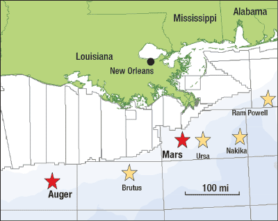
Shell E&P, Signa Engineering and At Balance Americas have been deploying Managed Pressure Drilling (MPD) for several years. The initial success in the GOM was at Mars Field in 2004.1 The lessons learned there were later applied at Auger Field, where similar problems occurred. Mars and Auger are in the deepwater GOM in 2,800-3,000 ft of water, southeast and southwest of New Orleans, respectively, Fig. 1.
 |
|
Fig. 1. Mars and Auger Fields are in the deepwater GOM in 2,800-3,000 ft of water, southeast and southwest of New Orleans, respectively.
|
|
Reservoir depletion in these mature fields caused drilling problems from rock stress redistribution. Hole stability still requires high mud weights, but fracture gradients are reduced in reservoir and non-reservoir rock at these locations. This article will review both projects to show how deployment and training efficiencies have improved the technology’s application.
WHY MPD?
Redevelopment drilling can maintain production rates, while adding reserves from unique drainage points. However, production creates a drilling condition where the mud weight needed for hole stability produces in an Equivalent Circulating Density (ECD) that cannot be supported by the rock, since the rock has been weakened by fluid extraction.
In deepwater fields, well geometry and depletion make new development drilling difficult because:
- Depleted sands and virgin-pressured sands occur together
- Altered pore pressure/fracture gradient curves narrow the drilling window
- High mud weights overbalance unproduced sands
- High ECD develops from mud density, depth and hole size.
Borehole stability must be maintained for the shale overburden and virgin-pressured sands. In conventional drilling, borehole stability is achieved with the mud density. Reduced fracture gradient is compounded in redevelopment sidetracks, when the existing well geometry yields higher ECD than the original drilling. Increased ECD with the original mud density requires a wide drilling margin, which conflicts with the narrower margins created by depletion.
MPD applies controlled annular surface pressure to maintain a constant BHP, usually with a lower than normal mud weight. This can be done in an over- or underbalanced state by adjusting surface backpressure, as the circulation rate is varied.
MARS PROBLEMS
In 2004, Shell applied an automated BHP control system, known as Dynamic Annular Pressure Control (DAPC), developed by Shell International R&D, to overcome lost circulation and hole instability problems after two failed sidetrack attempts at Mars. DAPC was used in the third sidetrack attempt of the Mars A-14 well to keep Equivalent Circulating Density (ECD) within a narrow pore pressure/fracture gradient window. The lighter mudweight used with applied surface pressure approached the tight pore-pressure-to-fracture-gradient window, allowing deeper penetration before setting casing.
Mars A-14 was drilled and completed in 1996 in the M2 sand. The M1 sand was added in 2000. In May 2003, the well was shut in because of dropping oil production and increasing sand production. In 2004, the company decided to recover the slot and re-drill to the original reservoirs. The tubing and tieback were recovered, a whipstock was set and the well was sidetracked. An intermediate 9 5/8-in. × 11 7/8-in. expandable liner was set at 14,330-ft MD.
Sidetrack 1 reached 21,144-ft TD (16,340-ft TVD). It had departed 10,116 ft at 56°
inclination when lost circulation occurred. This destabilized the hole and led to a BHA loss.
After unsuccessful fishing, the hole was plugged back and a second sidetrack was attempted. Hole instability and lost circulation problems prevented an expandable liner from reaching the planned depth. A breach was discovered in the 9 5/8-in. x 11 7/8-in. expandable liner near the whipstock.
The post-mortem pointed to rock stress redistribution from depletion as a probable cause of the drilling problems, supported by casing damage in the original wellbore far from compacting sands, hole instability problems at formerly adequate mudweights and reduced fracture gradients.
MPD TECHNOLOGY
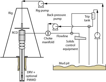
On the Mars TLP space was limited, so a custom MPD choke manifold was designed and manufactured. Surface backpressure was applied to the wellbore annulus using drillstring non-return valves, a Rotating Control Device (RCD), a dedicated MPD choke manifold and an auxiliary mud pump, Fig. 2. The manifold included one high-performance actuated drilling choke, isolation valves upstream and downstream, a gut line, and a check valve, to prevent backflow from the well to the auxiliary pump.
 |
|
Fig. 2. Surface backpressure was applied to the wellbore annulus using drillstring non-return valves, a rotating control device, a dedicated MPD choke manifold and an auxiliary mud pump.
|
|
An electronically resetable Power Relief Valve (PRV) with an independent power supply was connected below the RCD. The PRV acted as a safety valve to prevent formation damage from system overpressure, in the event of line plug from the RCD or in the manifold itself, failure of DAPC control or operational errors.
RESULTS
The well was drilled with a reduced mud density (13.1 ppg versus 13.4 ppg in ST01 and ST02), and the DAPC system maintained BHP pressure with a set point of 13.7 ppg. Full circulation was maintained and the hole was stable. At TD, mud density was increased from 13.1 ppg to 13.4 ppg for the trip out. The liner was run without incident and cemented with partial returns.
Using DAPC, BHP was maintained at 13.7 ppg EMW with rig pumps off, to avoid inducing excessive backpressure. The system was tested in the 95/8-in. section, where BHP control was adequate to drill with a reduced mud density through the reservoir section.
During most pump cycles, EMW was held between 13.5 and 13.9 ppg. There were a few low-side excursions associated with rig pump popoff and DAPC pump popoff events. BHP fell to static mud weight only once. The system would not have been suitable for drilling below pore pressure-losing backpressure due to low side excursions or PRV tripping would not have been acceptable with mud weight below pore pressure. There were a few excursions to the high side, approaching 14.0 ppg (0.3 ppg above set point) from ramping up the rig pumps. However, these were below the 14.3-ppg EMW where losses occurred in the first sidetrack.
Low and high spikes should not occur with the full DAPC system and pump-ramp control system. An After Action Review identified many quick fixes for the operational upsets. Overall, the system was found fit for the Mars A-14 ST3 well and it was critical to reaching the well’s objectives.
The system performed well and the engineers found that the set point needed to be a few tenths below circulating ECD for system backpressure and pressure spikes. Opportunities were identified to improve the hydraulics model, for example, modeling of the effect of pipe rotation on ECD. Many issues that developed were related to deploying a fit-for-purpose system on a fast-track basis.
AUGER PROBLEMS
The Auger TLP is Shell’s first deepwater GOM development, moored in 2,860 ft of water on Garden Banks Block 426. Production began in 1994 and has passed 500 million boe from five main reservoirs. This extraction has depleted reservoir pressure more than 5,000 psi.
Rock mechanics analysis concluded that the Auger depletion reduced fracture gradient due to stress redistribution in the sand and shale overburden, which narrows the drilling margin. Previous redevelopment sidetracks between 1999 and 2002 resulted in a success rate less than 30%. Only 2 of 7 sidetrack attempts on three well slots were successfully drilled, cased and completed. The trouble time and cost stopped sidetrack drilling and necessitated an in-depth review.
Post-well reviews found that lost circulation events were the root cause of failed sidetracks. Common operational events include ballooning, control drilling, tight spots, packoffs and mud weight reduction. These reaffirmed the tight drilling margin where the combination of mud weight and drilling ECD is larger than the available drilling margin.
MPD SYSTEM
The MPD system used on Auger provides automated control of surface applied backpressure, enabling reduction of surface mud weight to control ECD and maintaining a Constant BottomHole Pressure (CBHP) throughout the drilling process. MPD uses CBHP to maintain the same pressure on the borehole during all phases of the drilling process. When one variable causes BHP to increase or decrease, other variables are controlled to offset that change.
The Auger MPD reduced surface mud weight, based on ECD at drilling flowrate. CBHP is done with additional surface equipment to convert the wellbore into a closed system for drilling. Surface backpressure compensates for reduced BHP from mud weight reduction and any operation during drilling.
The drilling system must be understood and managed to accomplish CBHP. Key components include annular surface pressure, drilling fluid density and rheology, cuttings loading, annular friction, hole geometry, drill pipe rotation speed and tripping speed. While variables such as cuttings loading, drill pipe rotation and mud rheology can be adjusted to make small BHP changes, applying annular pressure using DAPC to replace annular friction loss is most important to a successful MPD operation.
Surface mud weight is adjusted to obtain the desired ECD in drilling mode, and the MPD set point is accomplished with surface backpressure on the borehole during a connection. The MPD connection set point is slightly less than the drilling ECD to provide a safe tolerance for variation in applied backpressure.
The risks introduced with MPD are either over-pressure or under-pressure events. Over-pressure events exceed the fracture gradient and induce ballooning or lost circulation. Under-pressure events reduce BHP below borehole stability or pore pressure, resulting in hole collapse or flow. Hazard identification is the critical planning component of the MPD system design to develop reaction plans for safely avoiding and securing the well. The additional cost of MPD is far less than the recovery cost of lost circulation, a possible redrill and the deferred production from borehole trouble events.
MPD SYSTEM DESIGN
For slimhole sidetracks conducted inside the existing production casing, Auger uses a surface BOP stack installed on top of a dual-barrier production riser. Even though TLP movement is minimal, a slip joint and ball joint are required below the rotary table to tie the rotary housing to the BOP stack. This provides alignment over the stack and addresses environmental concerns by diverting any RCD mud leakage into the existing return mud flowline.
The DAPC system is automated and maintains a constant BHP at a programmed set point whether drilling, making a connection or tripping. At Auger, the system was programmed to maintain constant BHP during connections and tripping. Backpressure was not held while drilling ahead, since the designed flow rate provided adequate ECD for borehole stability.
The system used had three major pieces of equipment: a choke manifold, a backpressure pump and an Integrated Pressure Manager (IPM). Under the control of the IPM, the choke manifold makes continuous backpressure adjustments to maintain the set point. Precise BHP control is accomplished using continuous flow into the choke manifold from the backpressure pump while the rig pumps are off.
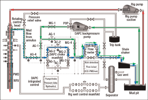
The choke manifold consisted of two primary 4-in. hydraulic choke legs and one 2-in. secondary hydraulic choke leg. Under normal operation only one primary choke is active; the other acts as backup. The backup was programmed for static high-level pressure relief to protect the wellbore against over-pressure events. Figure 3 shows the MPD flow schematic while drilling and connecting.
 |
|
Fig. 3. This MPD schematic shows the flowpaths while drilling and connecting: circulating (red), drilling (blue), connection (green) and backpressure (multicolor).
|
|
All three chokes are hydraulically gear-driven position chokes activated by a Hydraulic Power Unit (HPU) mounted on the manifold. The HPU can be powered from multiple sources in case of malfunction. Primary power is supplied by an electric motor and secondary power by rig air supply. In the unlikely event both fail, manual power is available by recharging the accumulators, while maintaining the programmed set point under automated control.
The second component is the backpressure pump. Similar to the choke manifold, operation is under full control of the IPM. The pump provides dedicated, on-demand backpressure whenever the rig pump’s drilling flow rate drops below a defined threshold. The pump delivers a steady flow of mud into the choke manifold to actively stabilize BHP during connection transitions. BHP can also be increased or decreased during a connection by changing the set point in the IPM.
Measurement, monitoring, analysis and control are integrated into the third component, the IPM. The IPM consists of a control computer, a programmable logic control system, a real-time hydraulics model and data communications network.
Accurate BHP control requires a steady stream of accurate data. Regularly updated drilling parameters and real-time data from the pressure-while-drilling (PWD) tool are transmitted over a network to the IPM.
The rig pump stroke counter is of particular importance. The IPM uses the pump strokes as its indicator that the pumps are working, mud is flowing and that there is annular friction in the wellbore. Two independent counters are used to reduce the chance of data interruption or mechanical failure and ensure an uninterrupted data supply. As a contingency, the control system technician can manually enter the stroke rate.
The hydraulics model runs continuously to provide the IPM with calculated data to maintain the set point. Using the model and the manually entered stroke rate, the IPM will still generate the required DAPC system configuration and continuously control BHP.
Installed downstream of the DAPC choke manifold is a mass flow and density meter providing measurements of all flow through the system. The density measurement monitors gas levels in returns and provides quick return-mud density detection, when weighting up or cutting back the mud system.
ENGINEERING IMPROVEMENTS
Downhole pressure fluctuations will occur in every MPD well. To maintain a constant BHP set point, the IPM controls fluctuations within a safe operating tolerance spread. Initially, the BHP allowable tolerance was required at +/-0.3 ppg of the set point, but as improvements were made to the system the variability was reduced down to +/-0.2 ppg.
A significant improvement involved BHP control directly through the active primary choke. In the original IPM, mud return from the well flowed through one of the primary choke legs, while the backpressure pump flowed through the secondary choke leg. This early-version IPM used the secondary choke to manage backpressure during a connection, while the primary choke legs were closed and inactive. While effective and reliable, the rig pump transition during a connection required an extended transition from primary to secondary choke control. This process increased connection time from the steps needed to make the transition. The change to backpressure control through the active primary choke resulted in MPD connection time equal that of a conventional drilling operation and improved BHP control accuracy.
Backpressure control through the primary choke also enabled the secondary choke to be used for protection against over-pressure events. This new capability allowed the DAPC system to manage the pressure relief operation and eliminate potentially damaging pressure spikes from relief valves. The new IPM function for the secondary choke allows tracking of the increase and decrease of surface backpressure during a connection with a variable relief mechanism.
On the initial Auger wells, approximate calculations were made and downhole circulation rates were reduced, once the PWD signal was lost. Analysis of recorded PWD data concluded that BHP was maintained within 0.2 ppg. Unfortunately, 0.2 ppg was above the minimum fracture gradient and seepage losses occurred. Improvement was secured by preparing a circulation rate schedule accounting for hole geometry changes and annular friction losses based on hydraulics modeling. Results from recorded PWD of the latter weight ups revealed that constant BHP occurred with a 0.1 ppg fluctuation within the pressure window.
MPD provides the ability to almost instantly increase BHP to stop additional influx. Upon detecting an influx, annular pressure can quickly be added to a safe margin below the minimum fracture gradient. This can be done either while drilling at full circulation rate or when ramping down the pump to zero by adding the same incremental pressure to pressures used during the connection pump ramp down sequence. Shut-in procedures were prepared to add pressure while ramping down the downhole pumps prior to shutting the BOP. Since an influx can quickly be eliminated prior to shutting in the BOP stack, an improvement exists compared to taking additional influx during a shut in on conventional drilling operation.
EXECUTION IMPROVEMENTS
Understanding MPD fundamentals and how to react to unplanned events form the foundation MPD training. The most difficult aspect of MPD training is ensuring the wellsite drilling personnel develop a high confidence level that they can accurately respond without hesitation to unplanned drilling events. Trainers took a real-time operational approach. MPD engineers supervised the operation and continuously discussed “what if” possibilities with each crew. Unplanned events were minimal for the Auger program, but when there was an occurrence, the correct reaction was taken to safely secure the well.
MPD equipment rig-up time was significantly reduced after the initial well. Due to deck space and load limitations, each well required rig up and rig down of all MPD equipment. About 600 ft of 2-in. and 4-in. steel piping was required for the rig up. Prior to rigging down from the first well, all of the piping was coded and photographs taken of the equipment layout. On subsequent wells the configuration was reinstalled at a fraction of the rig-up time.
RCD installation was performed off line while the BOP stack was on the stump, then set on the well as one unit. This eliminated critical path time for RCD installation. The piping layout was improved to test the on deck MPD equipment without the RCD, which reduced testing once the RCD was installed.
The DAPC system is calibrated at the beginning of every job and prior to the start of MPD operations. This tunes the chokes for optimum performance at zero and maximum flow rates and defines the connection ramp-up and ramp-down sequence.
A backup to the DAPC backpressure pump was added for risk mitigation and system reliability. The drilling flowrates of the slimhole sidetracks only required one of the three rig pumps.
Continuity of the drilling team was vital for success on the Auger MPD wells. Crews that started the first well finished the last well. MPD equipment and technology evolved from novel to normal operations.
RESULTS
MPD on Auger achieved constant bottom hole pressure control throughout the drilling process to manage the tight drilling margins created from redevelopment drilling challenges of:
- Depletion induced fracture gradient reduction within producing intervals and shale overburden
- Adequate BHP for borehole stability and well control in virgin formations
- Increased annular friction pressure of drill pipe by casing geometry, yielding excessive ECD over surface mud density.
To date on Auger, over 10,000 ft has been successfully drilled on four sidetracks without lost circulation or formation influx using an automated MPD system. This represents over 140 pump cycles in which 99% of the automated cycles were performed within the set point tolerance.
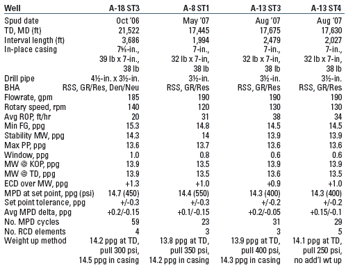
Table 1 summarizes the four redevelopment sidetracks drilled with MPD on Auger. The Auger A-18 ST3 well was the first MPD well in the redevelopment campaign. The target was an up-dip location in a virgin pressure reservoir fault block. The required sidetrack depth, however, was above a known depleted reservoir, thus presenting lost circulation risk, if drilled with conventional mud weights and the expected drilling ECD. The sidetrack was drilled with surface mud weight reduction of 0.4 ppg, effectively reducing the drilling ECD safely below the minimum fracture gradient. The mud weight used provided primary well control, but was less than that required for borehole stability.
| TABLE 1. Auger MPD sidetrack wells |
 |
|
The second sidetrack, Auger A-8 ST1, targeted attic locations of two depleted reservoirs. Previously determined un-drillable due to the available drilling margin of 0.8 ppg and expected ECD of 1.0 ppg over surface mud weight, the MPD system allowed surface mud weight reduction of 0.5 ppg for the sidetrack. The surface mud weight was 0.2 ppg below pore pressure for the deeper half of the interval. This well was successfully drilled, weighted up and cased without a lost circulation or influx event by maintaining a CBHP with the MPD system.
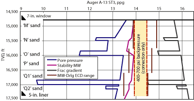
The third sidetrack, Auger A-13 ST3, was added to the campaign after successful execution of the second sidetrack, A-8 ST1. Well A-13 ST3 targeted a severely depleted up-dip target, while having to penetrate three depleted zones. It had the tightest drilling margin of 0.6 ppg at TD through the target, Fig. 4. The surface mud weight approach varied from the previous wells in that mud weight was reduced by 0.3 ppg while drilling the section. This was due to the trip mud weight needed at the kick-off depth after the window milling operation. There, the TD mud weight was equal to known pore pressure. The zone was uneconomic, so the hole was plugged for an immediate sidetrack.
 |
|
Fig. 4. Well A-13 ST3 targeted a severely depleted updip target, while drilling three depleted zones with a drilling margin of 0.6 ppg at TD.
|
|
The fourth sidetrack, Auger A-13 ST4, had the same available drilling margin as ST3. Again, the mud weight was successfully reduced by 0.4 ppg while drilling the interval and reached TD with surface mud weight 0.1 ppg less than pore pressure. Commercial pay was encountered and the well was weighted up and cased for completion.
Borehole trouble events caused from lost circulation or stability were completely avoided in the four MPD sidetracks. The last wells added otherwise unattainable reserves and production using the DAPC system.
Consistency of personnel was the key to improvements in the MPD system and to the success of each sidetrack. MPD equipment rig-up time was 100% offline after the first well. Online pressure testing of the MPD system was reduced to one test after the RCD element was installed. Cased hole calibration of the MPD system was reduced to less than six hours, a 50% improvement. MPD contingency training was incorporated with system calibration after the first well. MPD connection time improved over 40% to the equivalent of a conventional drilling connection.
Critical backup systems were added to reach 100% uptime. Flow meter accuracy improvements were made to enhance connection gas and kick detection monitoring. RCD element change outs improved to less than one hour and eliminated under- and over-pressure variations. Weight ups of 0.5 ppg were done without lost circulation by maintaining BHP.
The proactive approach to MPD enabled proper planning and training time, in addition to focus on continuous improvement of the system and its operability. Based on GOM success, Shell is now using the system in Canada, Europe, Africa and the Middle East. 
ACKNOWLEDGEMENTS
The authors thank Shell for permission to publish this article. The entire Auger wellsite rig team deserves special thanks for their positive attitude and focus on continuous improvement of MPD. This paper was prepared in part from IADC/SPE 112662 which was presented at the 2008 Drilling Conference in Orlando, Florida, March 4-6, 2008.
LITERATURE CITED
1 Roes V., Reitsma, D., Smith L., McCaskill J. and F. Hefren, “First deepwater application of dynamic annular pressure control succeeds, “ IADC/SPE 98077, presented at the IADC/SPE Drilling Conference in Miami, Florida, February 21-23, 2006.
|
THE AUTHORS
|
| |
Mark Chustz earned a BS degree in chemical engineering from Tulane University. He is an active member in AADE and SPE, and is Shell’s technical representative on the DEA-155 Joint Industry Project and the LSU Consortium on Well Control for Managed Pressure Drilling. Chustz has spent his career in deepwater GOM drilling and completion operations and is presently responsible for the Auger TLP as Staff Drilling Engineering for Shell Exploration & Production Co.
|
|
| |
Larry Smith earned a BS degree in engineering from Texas A&M University and is a registered professional engineer. He has spent 37 years managing development and exploration drilling projects, domestically and international. Since joining Signa in 2003, he has worked primarily for Shell providing engineering and operational support for MPD projects in the deepwater GOM, South Texas and Canada. Smith is a Senior Project Drilling Engineer for Signa Engineering in Houston, Texas.
|
|
| |
Dwayne Dell earned a BS degree in power engineering from Southern Alberta Institute of Technology. He has13 years’ experience as a wellsite supervisor in underbalanced and MPD operations. He joined At Balance in 2006 as a Managed Pressure Drilling Supervisor and has overseen preparations and operations during the first application of MPD by many operators, including the MPD wells drilled at Auger. Dell is North America Operations Manager for At Balance in Houston, Texas.
|
|
|


