Elongated, oval-shape probe/pad assembly includes many dual packer benefits without its limitations.
Chris Jones and Wandi Alta, JOB Pertamina-Hess Jambi Merang; Jorawar Singh, Bob Engelman, Mark Proett and Bob Pedigo, Halliburton Energy Services
Collecting representative, single-phase retrograde gas samples from heterogeneous fractured carbonate formations is challenging, especially for cases in which the reservoir pressure narrowly exceeds the dew point. Conventional wireline probe/packer assemblies are undesirable in this situation because their small-diameter probes increase the pressure drawdown compared with other available intake configurations. Furthermore, the likelihood of establishing hydraulic communication with an open fracture or vug is low with a ½-in. diameter probe compared to setting straddle packers spanning a 1-m formation interval.
Inflatable straddle packers can be run with pump-out test tools, but they have temperature, pressure and operational limitations. Like a straddle packer, the new Oval Pad tool is effective when testing thinly laminated and tight formations, as well as fractured or vuggy carbonates. The oval shape enables the pad to encompass a significant vertical length of the borehole while establishing a pressure seal with the formation.
JAMBI MERANG FIELD
A retrograde gas reservoir is contained within the vuggy carbonates in the Jambi Merang area of South Sumatra. The Jambi Merang Block was awarded in February 1989. Since then, 10 wells have been drilled, of which six were exploration and four were delineation, Fig. 1. The carbonate in the South Sumatra Basin comprises buildups on carbonate platforms along with the marine shale equivalent. The platform limestones are micritic and tight, while the carbonate buildups form the reservoirs. Porosity is predominantly created by meteoric waters at the top of the carbonate buildups, hence the traps are typically stratigraphically controlled by the diagenetically developed porosity distribution. The platform carbonates generally form on the shelf of the Sunda Craton with the buildups developing on the platform. In the Jambi Merang Block, the carbonate platform is isolated from the palaeo-coastal fringing platform limestones and is situated high on the Merang Block. On this isolated carbonate platform, there is a series of buildups, one of which is Sungai Kenawang.1
 |
|
Fig. 1. Location of the Jambi Merang Block, with the red areas indicating the gas/condensate field.
|
|
The carbonate reservoir is a 700-1,000 ft thick retrograde gas reservoir with a bottom aquifer drive. JOB Pertamina-Hess Jambi Merang drilled two exploratory wells with the primary objective of enhancing formation evaluation. The evaluation program involved openhole logs, core analysis and sampling. Openhole logs included standard resistivity, density, neutron, sonic and spectral gamma ray in addition to electrical micro imaging.
Pressure testing, sampling and fluid analysis were an important part of the formation evaluation program. A single-phase gas sample was necessary for future production planning. It was anticipated that the dew point would be no more than 50 psi below the formation pressure. Obtaining representative gas and condensate samples is always challenging. In this case, the plan was to keep the drawdown differential pressure at the sandface to only 20 psi below the formation pressure.
FORMATION TESTING AND THE OVAL PAD
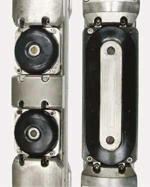
Modern pump-out wireline sampling tools were introduced in the early 1990s and included single or multiple probes, Fig. 2. Most of these Wireline Formation Testers (WFT) offer probes in the ½-in. to 1-in. diameter range, with some probes as large as 2 in. Sampling in highly heterogeneous formations still represented a challenge for WFT, and soon after the pump-out tools were introduced, straddle packers were adapted. Dual Straddle Packer Systems (SPS) offer advantages over probes in low-permeability applications as well as in heterogeneous environments because of the large borehole area exposed for sampling.
 |
|
Fig. 2. The new dual-probe oval pad tool on the right compared with conventional dual-probe pads. The oval pad exposes nearly 10 in. of formation.
|
|
In carbonates, thinly bedded sands and naturally fractured reservoirs, most of the production occurs from small features, which makes sampling and reservoir characterization difficult with a probe. The probe is more likely to be placed in a location that is characteristic of the rock matrix, which usually results in a tight test. The SPS typically isolates an interval of 1 m, which is normally ample to characterize heterogeneous rock.
The primary advantage of an SPS is its ability to cover a vertical interval where a probe is a pinpoint by comparison. A new probe concept, the Reservoir Description Tool (RDT) oval pad, is able to traverse a vertical interval but still retain the fundamental advantages of a probe. The oval pad can expose nearly 10 in. of vertical (or longitudinal) distance which is about one-quarter of a typical SPS interval.2
JOB PLANNING
Comparisons can be made between sampling systems over a range of operational conditions.2 This analysis can assist in the planning of WFT pump-out operations. Typical parameters for this analysis are shown in Table 1 with the simulation results in Table 2. Dual probes are shown because the RDT can use two closely spaced probes (7¼-in. spacing) that can sample from the same zone. In this case, the SPS would take only 30 minutes to inflate the packers, pump-out a sample and deflate, while the oval pad would take 1.5 hours. However, a single probe would take nearly 10 hours.
| TABLE 1. Job planning variables |
 |
|
Considering the testing plan objectives, the oval pad was selected for this reservoir. A primary reason for this selection was the extensive pressure survey planned. In this carbonate reservoir, WFT probe configuration had proven to be problematic, but the oval pad had been used successfully in other carbonate reservoirs.2 Conversely, straddle packers can be set a limited number of times for pressure testing and sampling before they become fatigued and unusable. They also have a higher risk of differential sticking. A single probe can flow at 0.6 cc/sec while the oval pad can flow at 3.75 cc/sec while maintaining a 25-psi pressure differential (i.e.,ΔPpout = Pformation - Pflowing), Table 2. The oval pad can flow over six times faster than a probe under these conditions. Also, because it traverses nearly 10 in. of wellbore, both pressure testing and sampling can be significantly more successful in these carbonate formations.
| TABLE 2. Job planning estimates for a 200 md/cp formation |
 |
|
PRESSURE TESTING
Two wells were drilled in the Jambi Merang Block to evaluate carbonate reservoir quality and hydrocarbon fluid type. Previous WFT fluid sampling attempts in these condensate reservoirs yielded multi-phase contaminant-bearing fluid. In these cases, the inlet flowing pressure was allowed to drop below the dew point, which induced unwanted liquid condensation in the saturated reservoirs. Allowing liquid condensation to occur in the pore system reduces the relative permeability to gas, in turn inducing additional pressure drop and liquid condensation. Collecting a gas sample above the dew point avoids both the unwanted phase separation and biasing the sample towards the higher mobility (k/µ, md/cp) light-end fluid components. This assures that the collection of representative samples contain all reservoir fluid components. Extensive pre-job planning was conducted to optimize the tool string for achieving low differential pressure during pumping and collecting single-phase samples.
The RDT consists of multiple sections that can be connected in numerous configurations for testing and sampling applications, Fig. 3.3,4 A typical configuration consists of a Hydraulic Power Section (HPS), Quartz Gauge Section (QGS), Flushing Pump Section (FPS), and Multi Chamber Sections (MCS).
 |
|
Fig. 3. The RDT configuration shows the normal through flow path and the bypass method.
|
|
During normal flow pumping, the fluid is routed through the Magnetic Resonance Imaging Laboratory (MRILab) and expelled to the borehole through the expulsion valve in the downstream MCS (lower MCS in pump-down case). The bypass flow method was developed for recording NMR T1 measurements on stationary fluid in the MRILab without affecting pump-out flow geometry. The pump rate is maintained during bypass flow, and the fluid is expelled through the MCS expulsion valve on the upstream side of the MRILab. bypass flow is used periodically to improve NMR signal-to-noise ratio and confirm T1 response.
A pumpdown mode was selected because it has proven to be the most effective configuration for sampling light oil and gas because the heavier contaminants tend to segregate naturally while flowing down rather than mix when pumping up. This phase segregation also improves the determination of fluid type and contamination estimations. The oval pad was selected to overcome common challenges associated with pressure testing and sampling heterogeneous and vuggy carbonate reservoirs with conventional probes that include establishing pressure seals with the formation and avoiding tight tests.
An MRILab tool section was used for contamination analysis and fluid probability determination while pumping. A popular approach to fluid identification is based on the optical properties of the fluids entering the tester.5 The MRILab Fluid Analyzer,6 on the other hand, offers an alternative based on the NMR properties of the fluids.7 The MRILab makes Saturation Recovery (SR) T1 measurements during the pump-out process, and contamination can be estimated in either time or relaxation domains. A wealth of reservoir fluid information is available from the RDT/MRILab combination including viscosity, diffusivity and hydrogen index.8
Well 1 openhole logs. Well 1 is a delineation well. Collecting and retrieving single-phase retrograde condensate fluid samples was established as a priority. Because the reservoir pressure could be equal to or slightly above the dew point pressure, a plan was developed to maintain the pressure differential between the reservoir and the inlet flowing pressures to less than 20 psi while pumping to clean up and collect a clean representative sample.
High-resolution electrical borehole images indicate a heterogeneous carbonate depositional environment where a condensate sample was collected. The pressure drop through the oval pad is less than the equivalent drop would be through conventional DPS probes at the same flowrate. The pre-job planning based on anticipated mobility, borehole overbalance pressure and maximum allowable drawdown pressure influenced the selection of the oval pad for this well over dual probes or straddle packers. The tool was configured to pump down, to enable the heavier WBM filtrate to gravitate downward through the pump and flowline and be cleanly flushed out to the wellbore.
Sample acquisition. Reducing the inlet pressure drawdown during pumping was achieved, to maintain the fluid above the dew point pressure. Sealing efficiently was comparable to a standard-probed WFT. Six samples were collected at four different depth stations; three sampling stations were gas-bearing and one was water-bearing. The oval pad pressure sealing efficiency on this well was 87%, a value consistent with 85% sealing efficiency attained throughout Indonesia.
Sampling and contamination analysis. Initially, the outlet pressure indicated some flowline plugging during the pump-out sequence, which was remedied by modulating the pump-out rate and selecting different outlet ports. The differential between formation and inlet pressure was maintained at about 15 psi, which was sufficient to maintain single-phase conditions above dew point.
Well 2 sample gas case. RDT configured with MRILab was used to collect a condensate sample in Well 2. The density caliper log indicated poor hole quality at the depth where the oval pad was set and the sample was collected, with very large washouts above and blow the sample point of X,609.1 ft. The pump rate was initially set low to minimize pressure drawdown. To maintain less than 20 psi drawdown, the maximum rate was set at 8 cc/sec at 1,000 sec.
Using FluidXpert, an analysis method that incorporates several sensor measurements to estimate contamination, the resulting fluid identification plot indicated a high probability of water flowing through the tool before the arrival of new fluid from the current pump-out station. The expectation was that the new fluid type was probably gas. Cleanup was relatively quick. The FluidXpert plot indicated contamination was less than 5% by volume at about 18 min into the pump-out.
Drillstem test. A Drillstem Test (DST) was performed after Well 1 was completed. The well was produced for six days and then shut in for a multirate Production Log (PL) test. A Bottomhole Sample (BHS) was taken during this initial flow period of the DST before the PL test was run. The PL was run under stationary conditions and two different rates to determine the volumetric contribution of fluid from the carbonate section perforated from X,965-X,085 ft in a 7-in. liner. Production volumetric results showed an abrupt density change near the center of the perforated interval corresponding to an apparent transition from fluid to gas at this point.
The volume flowrates from the fluid analysis revealed that there was very little production below the gas-to-liquid transition. The PL volumetric summary of two perforated intervals also showed the majority of the production from the upper interval, with both intervals producing gas in the production tubing near the perforations, Table 3. This observation strongly suggests that the formation gas was condensing in the wellbore due to the pressure drop and collecting below the fluid-to-gas transition point. This pattern of condensation means that the wellbore is acting as a separator and the downhole sample taken above the perforations may not be representative of the total production.
| TABLE 3. DST production log flow summary |
 |
|
SAMPLING RESULTS
The results shown in Table 4 are basically the conditions under which the samples were taken. Table 5 shows the conditions at the surface when the samples were recovered and also shows laboratory testing results including the dew point and heavy hydrocarbon composition (C7+ Mol %). As shown in Table 4, two RDT samples were taken in Well 1 (X,931 ft), and one BHS was taken during the DST above the perforated interval (X,964-X,979 ft). An additional Surface Stock Tank (STS) sample was taken, and the results are shown in Table 5. In Well 2, a single sample was taken (X,609.5 ft).
| TABLE 4. Downhole sample summary |
 |
|
| TABLE 5. Surface sample summary |
 |
|
Using the detailed compositional analysis of the RDT sample in Well 1, an Equation of State (EOS) simulation was developed using PVTsim.10 To test the sensitivity of the sample to the heavier carbon content (i.e., C7+, typically liquids), two additional PVT simulations are shown, one assuming 1% by molecular weight additional C7+ content and the other assuming 1% less. From this analysis it is clear that small changes in the heavy carbon content can dramatically affect the dew point. For this reason, it is critical that extreme care be taken to preserve a sample’s integrity when obtaining a sample as well as during subsequent handling.
CONCLUSION
This case study shows the results of successful application of the new wireline pump-out tester oval pad technology. Previous attempts to obtain representative WFT samples in this field were unsuccessful due to the fluid pressure dropping below the dew point.
The oval pad operates with a lower pressure differential than probes, and the RDT tool offered the rate controls necessary to maintain the flowing sample to within 20 psi of reservoir pressure. Samples were taken in two wells including an RDT sample, a production logging DST bottomhole sample, and a stock-tank sample. The RDT MRILab and FluidXpert were used to estimate contamination and determine when clean samples were to be taken.
Laboratory analysis of the samples revealed that the RDT samples were comparable with the PL DST bottomhole samples. An EOS PVT simulation based on the composition of the RDT sample demonstrated that the samples were within a reasonable error band. 
ACKNOWLEDGEMENTS
The authors acknowledge their respective management teams for granting permission to develop this article and exhibit the results. We also acknowledge Mickey Pelletier of Halliburton for his contributions. This article was modified from “Collecting single-phase retrograde gas samples at near dew point reservoir pressure in carbonates using a pump-out formation tester with an oval pad,” SPE 110831 presented at the SPE Annual Technical Conference and Exhibition held in Anaheim, California, Nov. 11-14, 2007.
LITERATURE CITED
1 Clure, J. and N. Fiptiani, “Hydrocarbon exploration in the Merang Triangle, South Sumatra Basin,” IPA01-G-10 presented at the Indonesian Petroleum Association, Twenty-Eighth Annual Convention & Exhibition, October 2001.
2 El Zefzaf, T., El Fattah, M. A., Proett, M. A., Engelman, B. and A. Bassiouny, “Formation testing and sampling using an oval pad in Al Hamd Field, Egypt,” SPE 102366 presented at the SPE Annual Technical Conference and Exhibition held in San Antonio, Texas, Sept. 24-27, 2006.
3 Proett, M. A., Chin, W. C., and B. Mandal, “Advanced dual probe formation tester with transient, harmonic, and pulsed time delay testing methods determines permeability, skin, and anisotropy,” SPE 64650 presented at the SPE International Oil and Gas Conference and Exhibition held in Beijing, China, Nov. 7-10, 2000.
4 Proett, M. A., Gilbert, G. N., Chin, W. C. and M. L. Monroe, “New wireline formation testing tool with advanced sampling technology,” SPE 71317, SPE Reservoir Evaluation & Engineering Journal, April 2001.
5 Mullins, O. C., and J. J. Shoroer, “Real-time determination of filtrate contamination during openhole wireline sampling by optical spectroscopy,” SPE 63071 presented at the SPE Annual Technical Conference and Exhibition, Dallas, Texas, Oct. 1-4, 2000.
6 Prammer, M. G., Bouton, J. and P. C. Masak, “The downhole NMR fluid analyzer,” SPWLA-2001-N presented at the SPWLA 42nd Annual Logging Symposium, Houston, Texas, June 17-20, 2001.
7 Masak, P. C., Bouton, J., Prammer, M. G., Menger, S., Drack, E., Sun, B., Dunn, K.J., and M. Sullivan, “Field test results and applications of the downhole magnetic resonance fluid analyzer,” SPWLA-2002-GGG presented at the SPWLA 43rd Annual Logging Symposium, Oiso, Japan, June 2-5, 2002.
8 Akkurt, R., Fransson, C., Witkowsky, J. M., Langley, W. M., Sun, B. and A. McCarty, “Fluid sampling and interpretation with the downhole NMR fluid analyzer,” SPE 90971 presented at the SPE Annual Technical Conference and Exhibition held in Houston, Texas, Sept. 26-29, 2004.
9 Pedersen, K. S., and P. L. Christensen, Phase behavior of petroleum reservoir fluids, Cat. #DK4661, CRC Press, Nov. 1, 2006.
|
THE AUTHORS
|
| |
Chris Jones is chief petroleum engineer for JOB Pertamina-Hess Jambi Merang and is based in Jakarta.
|
|
| |
Wandi Alta is a reservoir engineer assistant for JOB Pertamina-Hess Jambi Merang in Jakarta.
|
|
|
|
Jorawar Singh is Halliburton’s technical manager for wireline and perforating services based in Jakarta and was involved in the implementation of the pump-out formation tester in Indonesia. He joined Halliburton in 2000 as general field engineer and held operational and field management positions before becoming technical manager. Singh graduated as an electronics engineer in India in 1990 and worked in India’s national oil company as a logging engineer before joining Halliburton.
|
|
|
|
Bob Engelman is pressure testing and sampling global product champion for Halliburton Wireline & Perforating Services. After studying mechanical engineering at MIT and the University of Colorado, he earned a BSME degree and began an oilfield career in 1980 as a logging field engineer in the Rocky Mountains. He has held multiple technical and management positions over the past 28 years.
|
|
|
|
Mark A. Proett is a senior scientific advisor for Halliburton Energy Services in the Strategic Research group. He received a BSME degree from the University of Maryland and a MS degree from Johns Hopkins. He has been involved with the development of formation testing systems since the early 1980’s. Proett holds 40 patents, 36 of which deal with well testing and fluid flow analysis methods. He has served on the SPWLA and SPE technical committees and served as the Chairman for the SPE Pressure Transient Testing Committee. Proett also served as an SPWLA distinguished speaker in 2004 and as an SPE distinguished lecturer in 2006-2007.
|
|
| |
Bob Pedigo is the business segment manager for Halliburton Energy Wireline Services in Jakarta, Indonesia. He received his BS degree in geology from Ball State University before joining Halliburton in 1984. As a master field engineer, he led the introduction of SFTT/RDT testing services for Venezuela where he also worked with the formation evaluation group and supported BP as a technical advisor. He moved to Indonesia in 2003 as a service coordinator to introduce RDT testing and fluid analysis services for a start-up operation in Balikpapan.
|
|
|


