Three-year DEA development program and field tests result in spall-resistant, high-performance, fourth-generation hardband
Alvaro Chan, Dan Hannahs, Michael J. Jellison, Grant Prideco; Michael Breitsameter,
Daniel J. Branagan, Nano Steel Co.; Harvey Stone, Noble Drilling (Canada) Ltd.;
and Greg Jeffers, Nabors Drilling USA LP
Today, the focus is on protection of both casing and drillstem components in both cased and openhole conditions. The result of this 36-month development program is a fourth-generation spall resistant, high-performance hardband. The innovative laboratory testing program surpasses the earlier DEA 42 methodology and provides repeatable and accurate prediction of the hardband’s wear performance. The test concludes with field trials.
Advanced nanotechnology and a systematic design approach enabled the manipulation of material properties to yield a spall-resistant hardband that offers superb drillstem wear resistance and casing wear protection while reducing friction. These materials are ideally suited for today’s long and complex drilling programs where extended drilling through casing is required.
This article reviews the historical changes in drilling practices, development of drillstem hardbanding materials, and their shortfalls in meeting the industry’s needs. Also presented are recent developments in laboratory testing to repeatedly predict hardband/tool joint wear performance. Finally, the development, laboratory testing and field trial of a fourth-generation hardband material is described.
INTRODUCTION
Casing-friendly hardfacing materials must be developed to extend the life of the drill pipe while protecting the casing. For decades the industry has used traditional materials such as tungsten carbide, chrome carbide, and other alloying elements to improve the abrasion resistance on tool joint components. These materials, in some cases, have demonstrated exceptional performance to drill pipe wear but are not good at protecting the casing. Typical materials are good at protecting either the drill pipe or the casing but not both. The solution to develop new materials must span both sides of the spectrum at the same time.
BACKGROUND
Hardfacing materials have been used in the industry since the late 1930s. The first hardband materials consisted of a mild steel matrix with crushed sintered tungsten carbide particles. Slowly, with more complicated well designs, casing failures became increasingly common. A change to pelletized tungsten carbide particles was made to reduce the abrasive properties of earlier hardfacing materials.
The industry gave out hope on hardfacing materials for a while and decided to abandon the application. It quickly discovered there were a couple of problems: The steel of the drill pipe tool joints caused more wear on the casing due to the galling action. It took more than sixty years since the initial development of hardfacing materials for the industry to respond to the new challenges and come up with new alternatives to tungsten carbide.
In the early 1990s, chromium hardfacing materials were introduced to the industry. These materials offered good casing protection but did not perform well in open hole sections. With increased drilling of horizontal and Extended Reach Drilling (ERD) wells, the need to improve the resistance arose. Following attempts at improving performance used chrome alloyed materials that offered some improvement but still lacked the desired performance.
Materials such as tungsten carbide (WC), and chrome (Cr) alloys have been extensively used in the industry. They offer great drill pipe wear resistance but poor casing wear protection. Casing friendly materials typically are iron based alloys with additions of Cr, manganese (Mn), molybdenum (Mo), nickel (Ni), boron (B), and Niobium (Nb).
There was also the need to offer easy re-application, robust adhesion, and longevity to the hardfacing material, factors not always achievable with traditional materials. To complicate matters more, there is a lack of hardfacing material evaluation guidelines by the industry, a direct effect of the rapidly evolving drilling programs and the slow response of the industry to catch up and meet the challenges.
MATERIAL DEVELOPMENT
To provide the industry with a casing-friendly hardfacing material, a new methodology was used to obtain targeted results. New alloys with exceptional properties were developed.
Several base materials were initially considered for development into casing-friendly hardfacing material. They were analyzed and evaluated based on mechanical and metallurgical properties, abrasion, toughness, spalling resistance and performance. The testing procedures subjected the candidate materials to destructive analysis that included adhesion and abrasion testing. New testing methods were developed to reflect more accurate evaluation conditions than those provided by industry standards such as the DEA 42.
Once a base material was pre-selected according to its performance, several iterations of variations in alloys and alloy content were performed to further improve the performance characteristics. The selected material was a stainless steel base material alloy that was produced under new heat treatment processes.
EXPERIMENTAL PROCEDURE
The hardfacing material development used a Gas Metal Arc Welding (GMAW) process. The weld parameters were typical of those utilized in the industry with 248 to 280 A current, 25 to 28 V voltage, and utilizing 100% CO2 as the cover gas at 25 to 40 ft3/hr. Single pass welds were applied to the tool joint samples made out of 4137 modified steel. The developmental testing included: hardness measurements, Scanning Electron Microscopy (SEM) for microstructure observations, Energy Dispersive Spectroscopy (EDS) and X-Ray diffraction (XRD). The XRD scans were ran for 9-hr periods to avoid noise and enhance the peak-to-background resolution. In addition, other evaluation test such as density measurements, thermal expansion and impact Charpy toughness were performed.
ALLOY DESIGN
Based on an existing experimental database and previous trials on drillstem components, a nine-element iron-based glass forming alloy was developed and produced in cored wire form and extensively welded. This alloy was designated GPT10 for internal tracking purposes. While the alloy met many of the internal weldability, hardness, and wear requirements, trials revealed significant cracking on the tool joints. This downselected alloy was then used as a baseline material for further alloy design in order to provide the engineered fourth-generation hardbanding solution.
The task was to engineer a solution to maintain the favorable characteristics found such as hardness and wear resistance while maintaining glass forming ability and the achievement of near nanoscale structures and simultaneously improving the crack resistance. Since the focus was on improving crack resistance, an extensive study was launched to match the Coefficient of Thermal Expansion (CTE) of the weld overlay to that of the base metal, which is a No. 4137 modified steel. Through studying the effects of alloying elements on CTE changes in conventional metallic alloys, it was realized that specific combinations of elements exhibited the biggest effect on CTE. Based on this, several series were developed which involved producing a number of alloys with specific linear cuts in the nine-dimensional composition space. In the GPT series of alloys, seven alloy chemistries were designed along a specific linear cut in the composition space resulting in the following incremental alloys: GPT5, GPT7, GPT10, GPT13, GPT15, GPT17 and GPT20.
NANOSCALE MICROSTRUCTURE
Materials are composed of several basic phases or microstructures. These microstructures give the materials their unique mechanical properties and performance. Typical microstructures for steels have dimension in the scale of hundreds of microns to several millimeters; a micron is equal to 1E-6 m. Nanoscale materials according to ASTM E 2456-06 “Terminology for Nanotechnology,” are defined as those achieving a length scale from 1 to 100 nm, where a nanometer is measured as 1E-9 m, or 1,000 times smaller than a micron scale. There are several factors which influence the generation of extra-fine microstructures such as the ones in the nanoscale. By having extremely fine grain structures, the materials can exhibit mechanical and behavioral properties that far exceed those of standard materials.
ALLOY DOWNSELECTION/THERMAL EXPANSION STUDIES
For each undiluted alloy sample, the thermal expansion was measured from room temperature up to 1,000°C. Since the thermal expansion is not linear with temperature, rather than simply the measure of the coefficient, the difference in misfit strain was calculated as a function of temperature for each alloy and compared to that of the base 4137 modified substrate. Equation 1 depicts the strain equation:
Where is the misfit strain, is the misfit strain,  is the coefficient of thermal expansion and is the coefficient of thermal expansion and  is the temperature difference. is the temperature difference.
For the temperature difference, the reference temperature was taken as 25°C. Since cracking occurs during cooling after solidification, the misfit strain was graphed for each GPT series alloy from 100°C to 700°C, Fig. 1. The overall misfit strain can be calculated as the area under the curve (positive or negative) for the different alloys. It can be seen that the GPT5 alloy exhibits the highest misfit while the GPT15 alloy exhibits the lowest misfit.
 |
|
Fig. 1. Misfit strain versus temperature comparison for GPT alloys in 4137 base plate.
|
|
HARDNESS
One aspect of the alloy design stage was to maintain the favorable hardness/wear resistance of the GPT10 alloy. Table 1 presents measured density and hardness values for each GPT series alloy in the undiluted condition. The density of the alloys was found to vary from 7.42 to 7.60 g/cm3 in a well behaved fashion indicating no abrupt changes in microstructure or phase formation were occurring. The microhardness was found to decrease with increasing ‘T’ (GPT5-GPT20) number which corresponds to decreasing interstitial content and increasing Group VI transition metal content. The biggest drop in hardness was found to occur from the GPT13 and GPT15 chemistries.
Alloy downselection was based upon considering several important factors including achieving sufficient weld hardness for necessary casing and tool joint wear resistance and developing high crack resistance, which is affected by the stress generated due to differential thermal contraction during welding. Based on the hardness data, alloys above GPT15 exhibited hardness values below that necessary to achieve the targeted wear resistance. Although the GPT15 alloy exhibited the best misfit strain match for all alloys, it would result in a weld overlay material which was too soft. The prime candidate to offer both characteristics was a chemistry in-between the studied GPT13 and GPT15 alloys, designated as GPT14, which would be expected to exhibit the overall best CTE match while maintaining high hardness within the targeted range.
Crack Resistance. The adequate way to test for crack resistance of the hardfacing material is to weld it on to the tool joints, an impractical and cumbersome procedure. An alternative method that used a circular bead over a plate was devised for practical purposes. The test consisted in applying a circular bead 4 in. in diameter onto an 8-in X 8-in test plate of A36 steel. This simplified test did not replace the crack resistance test applied over actual tool joints that were later performed, it only helped in the evaluation of the materials.
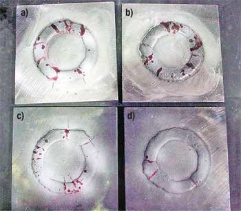
The GPT10 and GPT14 wires were tested under a pre-heat condition of 600°F and also with no pre-heat. Duplicate tests were performed for each condition. Visual inspection was performed by dye penetrant and the number of cracks calculated. Figure 2 shows the crack inspection for GPT14 alloy.
 |
|
Fig. 2. GMAW circular bead crack specimens showing cracks from dye penetrant inspection for the GPT10 alloy; a) No preheat, b) No preheat, c) 600°F preheat, and d) 600°F preheat.
|
|
Alloy GPT14 exhibited the least amount of cracking, approximately a ¼ of the amount for the GPT10 alloy under both conditions. Furthermore, the no pre-heat condition exhibited only one crack for the GPT14 alloy. This is a desirable characteristic for both Original Equipment Manufacturers (OEM) and also the weld tubular aftermarket where, unlike OEM manufacturing, the pre-heat temperature is difficult to control and maintain.
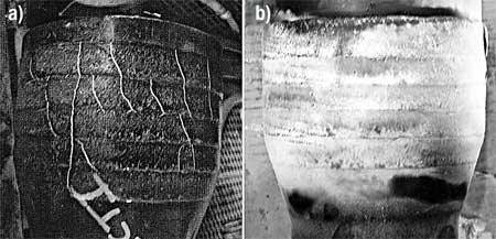
GPT14 GMAW Hardfacing Studies. Consistent to what was found in the GPT10 alloy, the GPT14 alloy was found to be readily weldable with industry standard parameters. Thermal expansion measurements were taken from GMAW GPT14 weld overlays from room temperature to 1,000°C. Figure 3 shows a thermal expansion comparison for the GPT14 alloy versus the 4137 modified steel base. As can be observed from the graph the thermal expansion match of the GPT14 alloy is very close to that of the 4137 modified steel as a function of temperature. This match was found to be superior over the already well studied GPT10 alloy. Figure 4 shows a comparison of both GPT10 and GPT14 applied hardband under visual inspection. As can be seen, the GPT10 alloy exhibits longitudinal cracks while the GPT14 alloy is crack free.
 |
|
Fig. 3. Thermal expansion as a function of temperature is shown for the 4137 steel substrate used for the tool joint and the GPT14 undiluted GMAW weld overlay.
|
|
 |
|
Fig. 4. Visual crack inspection; a) GPT10 showing the presence of cracks, b) GPT14 crack free deposit.
|
|
WELD OVERLAY PROPERTIES
Microstructural Development. GPT14 is a glass forming alloy designed with low critical cooling rates for metallic glass formation. An alloy that exhibits glass forming ability means it has an inherent resistance to nucleation during undercooling when cooling below its melting point, i.e. solidus. In other words non-glass forming alloys begin to nucleate, and grain growth occurs just a few degrees below the melting point. In contrast, several hundred degrees are required before nucleation for the glass forming GPT14 alloy. This allows GPT14 to develop extremely refined microstructures that can undergo elevated temperature exposure during welding while still maintaining a refined near nano-grain size.
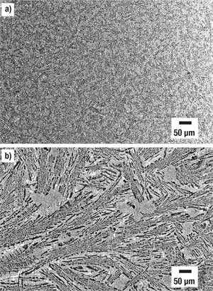
Microstructure. The microstructure of the GPT14 alloy was analyzed under X-ray diffraction to identify the phases present and SEM backscattered electrons were used to show the size and distribution of the phases present. Figure 5 shows both low and high magnification micrographs of the as-welded structure. The X-ray diffraction analysis showed the presence of complex (M)7(BC)3 borocarbide phases co-existing with a ductile matrix consisting of a-Fe.
 |
|
Fig. 5. Microstructure for GPT14 GMAW weld overlay; a) low magnification (100X), b) high magnification (1000X).
|
|
As can be seen from the micrographs, there are three microstructural constituents: primary dendritic phase (spherical light grey), two-phase lath eutectoid microconstituent regions (i.e. matrix), and a small volume fraction of transition metal enriched region (white) representing the last liquid to solidify. It is hypothesized that the a-Fe phase exists in two microstructural regions, as primary dendrites and also as a phase in the two-phase region of a lath eutectoid microconstituent consisting of a-Fe and (M)7(BC)3.
The key in structural refinement of the GMAW weld of GTP14, appears to be the significantly high undercooling achieved prior to nucleation and growth which results in a unique growth mode. In conventional overlay materials, dendritic growth modes are generally dominant leading to large microstructural scales. For the GPT14 alloy, the formation of primary dendrites can not be entirely avoided, nevertheless, the undercooling characteristics allow the material to undercool and grow directly into the coupled lath eutectoid microconstituent. The remarkable ability of the alloy to control nucleation and grain growth among other characteristics can be attributed to its native glass forming ability.
TOUGHNESS
The effective distribution of the microstructural phases such as the hard borocarbides coupled with ductile lath morphology appear to be especially potent for crack bridging, which in turn can provide high toughness along with high hardness.
There are several methods to determine hardfacing overlay toughness, however, some of those methods proved to be impractical or difficult to apply for this study. The option to estimate toughness through Charpy impact analysis was selected. Standard specimens (55mm × 10mm × 10mm) were used for this analysis. GPT14 alloy was overlayed over 4140 base steel which closely resembles the chemistry of 4137 steel utilized for tool joints. The samples were cut and machined so that ½ of the thickness was base material and ½ of the thickness was weld overlay. Charpy impact was done in triplicate with the striker impacting on the weld overlay side. None of the samples fractured when the maximum load for the impact machine of 60 ft-lbs was applied. The sample bent after the impact test and although one or two small cracks could be observed in the weld overlay, no delamination occurred.
HARDFACING EVALUATION AND METHODOLOGY
DEA-42 Methodology. One of the important baselines for wear studies was the project DEA-42 “Project to Develop Improved Casing Wear Technology.” This specification was developed several decades ago, and, while it provided a benchmark for evaluating casing wear, it had many limitations.
New drilling programs led to the development of improved testing methods that surpassed the original requirements of the initial DEA-42 specification. The goal was to provide the industry with data that was more accurate, repeatable and relevant than currently available methods and procedures.
Previous testing-equipment limits. The first attempts to evaluate wear performance in accordance with DEA-42 exposed many limitations on the testing equipment. The test fixture used a hinged table to support the tested specimen fixtures, creating a variance in the resultant applied force. This was an obvious source for error. The side load for this setup was measured with a pressure transducer, which, when coupled with the variations from the hinged table, provided inaccurate readings. The machine was limited to circulation of water. Circulation of drilling fluids was not possible. For the tested specimens, only the tool joint rotated while the casing remained stationary. The table was allowed to reciprocate while the tool joint rotated, again introducing load variations. The load fluctuated between 30 and 35% of the actual values. The setup only allowed for testing of hardfacing material to a casing. Alternative conditions, such as openhole, could not be tested. The specified casing grade was API N-80, an uncontrolled grade. Using an L-80 grade is more appropriate to eliminate variation in mechanical and metallurgical properties.
Second- and third-generation machines. To eliminate or minimize these issues, a second-generation machine and set up were designed. This next-generation machine included a free-floating table that allowed for the force to be perpendicularly applied to the tested specimen, eliminating all the variances of the first machine design. A load cell replaced the pressure transducer for measuring applied load.
Modifications to circulate drilling fluid were also added, providing more flexibility as well as more exact testing conditions. As for the mechanics, Variable Frequency Drives (VFDs) were incorporated into the machine in order to control RPM and mud flow. With all these improvements, the load fluctuation was reduced to 10-15%.
In addition there were requests for “openhole” testing capabilities. As a third generation machine was developed to expand testing capability.
To allow “openhole” capability, modifications to the testing machine included rotation of the testing medium or “stone” counter to the rotational direction of the tool joint. With this new setup, it was considered that for consistency purposes the casing material would be rotated in a similar fashion to that in cased-hole applications. This, in turn, eliminated the need for the table to move during testing. Linear slide bearings were added to the table setup in order to minimize table fluctuation, which was reduced to a 5-7% range. With the third-generation machine in operation, it was time to address sample preparation. The specimens were machined to controlled internal specifications in order to standardize the testing results and be able to truly compare “apples to apples” data.
Before all of this testing development, the standard for reporting hardfacing material characteristics was “wear factor.” With the integration of a torque disk into the machine, “realtime” torque values were now possible, allowing for “friction factors” to be determined for the first time from direct testing. One of the side effects of the improved testing machine was an extremely accurate and repeatable data collection.
FOURTH-GENERATION HARDBAND TESTING
DEA-42 Evaluation. To evaluate the performance of the fourth-generation hardfacing material, it was originally tested according to the DEA-42 methodology. Further testing used the third-generation hardfacing testing machine. The fourth-generation hardfacing material, GPT14, was evaluated against five other commercially available, casing-friendly hardfacing materials as well as with tungsten carbide and plain steel for casing wear and tool joint wear.
Figure 6 shows the results of the casing wear test, indicating that the fourth-generation hardfacing material achieved the lowest wear value of all tested hardfacing materials, including that of plain steel for the tool joints and for tungsten carbide. The fourth-generation hardfacing material achieved 4.9% of casing wall thickness loss. The closest comparison material achieved a 7.8% value, a 37% improvement to this nearest value.
 |
|
Fig. 6. Casing wear comparison.
|
|
Figure 7 shows the tool joint wear comparison. The fourth-generation hardfacing material obtained a 0.0020-in. radial wear of the tool joint inside the casing. This value is equal to that of plain steel from the tool joint. The closest compared value achieved was 0.0045-in. wear; i.e., the fourth-generation hardfacing achieved a 55% improvement over the closest casing-friendly material. Tungsten carbide was the only material that did not show any wear for the test.
 |
|
Fig. 7. Tool joint wear comparison.
|
|
The hardness comparison is presented in Fig. 8. Each hardness point represents an average of 5 hardness tests for the analysis. The graph shows that the fourth-generation hardfacing material has values of 629 HV (about 56 HRC) for the 100-g load and a 590-HV value (55 HRC) for a 300-g load. These hardness values for the fourth-generation hardfacing show that the material has an average value compared to the other casing friendly hardfacing materials.
For the CTE, the analysis considered two of the leading casing-friendly hardfacing materials. The analysis considered misfit strain as the measure for CTE just as it was originally considered during the development of the hardfacing material. The temperature considered ranged from 200°C to 1,000°C. Figure 8 shows the crack resistance as determined by the CTE. Again, the area under the curve is the amount of residual stress between the hardfacing material and the base metal. The larger the area (positive or negative), the greater the misfit and thus the higher the possibilities for hardfacing cracking and spalling. The fourth-generation hardfacing had the closest misfit strain to that of the base metal indicated by the horizontal line in the middle of the graph. The temperature range of interest for application that affects the misfit is located below 625°C.
 |
|
Fig. 8. Crack resistance as determined by Coefficient of Thermal Expansion (CTE).
|
|
Standard fracture toughness evaluation of the materials categorizes them into two main groups: high-toughness/low-strength materials and high-strength/low-toughness materials. High-toughness/low-strength materials typically have great resistance to impact but have low hardness. These are very ductile materials with low hardness. On the other end of the spectrum are the high-strength/low-toughness materials. These materials exhibit high hardness values but lack the ductility that offers good impact properties. The goal has been to harness the best properties from both of these materials while achieving high strength/high toughness from the same material. The development of nano alloying technologies has made this possible. Materials such as the fourth-generation hardfacing can offer both strength and toughness at the same time.
 |
|
Fig. 9. Strength and toughness.
|
|
THIRD-GENERATION CASING EVALUATION
After the fourth-generation hardfacing was evaluated in accordance with DEA-42 methodologies, it was subjected to further evaluation, this time using the evolved testing methodology that had improvements over reliability and repeatability.
Casing wear factor for the fourth-generation hardband has been calculated to 0.00103 in. per 1,000 revolutions (inches of wall thickness). The friction factor for the hardbanding was calculated to 0.75 in., and the tool joint hardband diametrical wear in casing was calculated to 0.00004 in. per 1,000 revolutions (on diameter) for the tool joint.
In addition to standard casing tests, the hardfacing material was evaluated for openhole conditions by using the flexibility of the third-generation testing machine and using stone as the wear medium. This value was calculated to 0.01216 in. per 1,000 revolutions (on diameter).
The final stage for the hardfacing material development consisted of an eight-month field trial beginning in October 2004. The hardfacing material was applied on NC50 connections for a 5.000-in., 19.50 lb/ft Range 2 S135 grade string. The hardfacing material was applied over 3-in. length (¾-in.-wide bands) at 3/32-in. raised condition with one extra band of ¾-in.-wide section applied to the 18° taper. The material was run for eight months and was inspected after 33,000 ft were drilled. The amount of wear was calculated at just above 0.020 in. Projecting a constant wear, it was estimated that a re-application would be required at around 100,000 ft of drilled-hole section.
CASE STUDIES
Since the launch of the fourth-generation hardband in late 2005, there have been more than 2 million ft of cumulative footage applied with this material. It has been put to use worldwide under severe conditions with no issues to date. Two case studies will be presented next from drilling contractors who have used the fourth-generation hardfacing material.
Noble Drilling (Canada) Ltd. has supplied the fourth-generation hardfacing product for the past year in Canada. Drilling 25,000-ft wells, horizontal and in difficult well conditions, the Hibernia project has exposed this fourth-generation material to extremely harsh conditions. More than 60,000 ft of this material has been put in service with favorable results and no issues. The material has demonstrated excellent performance even under these severe conditions.
Nabors Drilling USA LP has supplied fourth-generation hardfacing materials to more than 38 projects in North America, including California, Colorado, Texas, Oklahoma, Wyoming and the Gulf Coast. More than 19,000 joints (approximately 600,000 ft) of drill pipe with fourth-generation hardfacing, with a total of 6,265 running days, have been put in service by Nabors USA since late 2006.
CONCLUSIONS
The evolution of the drilling programs has put additional requirements on hardfacing materials. The shift has been made to hardfacing materials that offer both casing and pipe connection protection. New technological developments have made it possible to produce advanced materials that can offer protection to both casing and drill pipe components while maintaining performance.
Evolution of testing methods have also helped to better understand and evaluate hardfacing materials. These methods have shown significant improvement over traditional methods, providing more reliable and robust data.
New materials are currently under development to offer even better wear protection not only in cased holes but also under openhole conditions. Also, further improvements on testing methods are being developed to offer even more testing flexibility with improved accuracy. 
ACKNOWLEDGEMENTS
The authors thank Ronnie Hamby and Richard Griffin from Grant Prideco for their collaboration in this paper. The authors would also like to thank the management at Grant Prideco, The NanoSteel Company, Noble Drilling (Canada) Ltd. Corporation and Nabors Drilling USA LP for their support and encouragement in publishing this paper. This article was prepared from SPE 112740 presented at the IADC/SPE Drilling Conference and Exhibition, March 4-6, 2008, Orlando, Florida.
BIBLIOGRAPHY
API Specification 7, Specification for Rotary drillstem Elements, Fortieth Edition, November 2001, American Petroleum Institute, Washington, D.C., 2001.
API Specification 5CT/ISO 11960:2004, Specification for Casing and Tubing, Petroleum and Natural Gas Industries - Steel pipes for use as casing or tubing for wells, Eight Edition, July 2005, American Petroleum Institute, Washington, D.C., 2005.
Mobley, J.G, Hardbanding and its Role in Directional/Horizontal Drilling, SPE 52187, Presented at 1999 SPE Mid-Continent Operations Symposium, Oklahoma City, Oklahoma, 28-31 March 1999.
Mobley, J.G. Hardbanding and its Role in Deepwater Drilling, SPE 52882, Presented at 1999 SPE/IADC Drilling Conference, Amsterdam, Holland, 9-11 March 1999.
D.J. Branagan, “Enabling Factors Toward Production of Nanostructured Steel On an Industrial Scale”, J. Engineering Material Performance, 14(2005), 5-9.
D.J. Branagan, M.J. Kramer, Yali Tang, R.W. McCallum, D.C. Crew, and L.H. Lewis, “Engineering Magnetic Nanocomposite Microstructures”, J. Mater. Scien., 35 (2000), 3459-3466.
D.J. Branagan and Yali Tang, “Developing Extreme Hardness (> 15 GPa) in Iron Based Nanocomposites”, J. Composites Part A, 33 (2002), 855-859.
D.J. Branagan, W.D. Swank, D.C. Haggard, J.R. Fincke, “Wear Resistant Amorphous and Nanocomposite Steel Coatings”, Metallurgical and Materials Transactions A, 32A(2001), 2615-2621.
D.J. Branagan, “Engineering Structure on a Nanoscale Level To Achieve Targeted Properties In Steels”, CALPHAD, Calphad, 31 (2007), 343-350.
Daniel J. Branagan, Alla V. Sergueeva, and Amiya K. Mukherjee, “Towards the Development of a New Iron Age”, Advanced Engineering Materials, Volume 8, No. 10, 2006, 940-943.
B.E. Meacham, M.C. Marshall, and D.J. Branagan, “Palmqvist Fracture Toughness of a New Wear-Resistant Weld Alloy”, Metallurgical and Materials Transactions A, 37A, 3617-3627.
D.J. Branagan, M.C. Marshall, and B.E. Meacham, “High Toughness High Hardness Iron Based PTAW Weld Materials”, Material Science and Engineering A, 428(2006), 116-123.
C.G. Levi and R. Mehrabian, “Heat Flow During Rapid Solidification of Undercooled Metal Droplets”, Metallurgical Transactions A, 13A (1982), 221-234.
H.K.D.H. Bhadeshia, Bainite in Steels, Transformations, Microstructure, and Properties, 2nd edition, IOM Communications, Ltd. UK, 1001.
|
THE AUTHORS
|
| |
Alvaro Chan is area sales manager for South America at NOV-Grant Prideco. He has held the positions of marketing engineer, and metallurgist for Grant Prideco since he joined the company in 2002. He completed his education in 2000 and holds a bachelor’s degree in mechanical engineering, a master’s degree in mechanical engineering, and a master’s degree in metallurgical and materials engineering from the University of Texas-El Paso. He is a licensed professional engineer in the state of Texas. He is a member of SPE, IADC, ASM, AWS and NACE and has authored several technical publications in metallurgy and drilling applications.
|
|
| |
Dan Hannahs is manager of metallurgical engineering for NOV-Grant Prideco. He graduated from the University of Wisconsin-Platteville in 1989 with a BS in industrial management. He is a member of SPE and has authored technical publications in connection qualification testing and hardfacing materials.
|
|
| |
Michael Jellison is vice president of engineering of Grant Prideco’s Drilling Products and Services Division. He graduated with honors from Texas A&M University in 1980, with a BS in mechanical engineering. He initiated the effort at Grant Prideco to develop and manufacture 57⁄8-in. drill pipe. Mr. Jellison has published numerous technical papers for SPE, IADC, ASME and several trade journals. He served as a member of the editorial committee for the Journal of Petroleum Technology from 2000 through 2002. He is a registered professional engineer.
|
|
| |
Harvey Stone is rig superintendent for Noble Drilling (Canada) Ltd. Mr. Stone manages the offshore operations and helped develop and manages Noble’s drill pipe management plan. He joined Noble Drilling in 1996. He previously worked for Zapata Offshore, mainly on international assignments, which included drilling in the South China Sea, New Zealand, Australia, the North Sea and Brazil. Mr. Stone has extensive operational experience in drilling.
|
|
| |
Greg Jeffers is tubular and asset senior manager for Nabors Drilling USA, LP. He manages all forecasting, purchases and policies of tubulars for Nabors Drilling USA. Mr. Jeffers joined Nabors Drilling USA in 2002. He has previously held supply chain management positions at El Paso Global Networks - El Paso Energy, Splitrock Services - McLeodUSA, and Cytex Plastics - RDC/Cytex. He earned a bachelor’s degree in accounting in 1995 from Sam Houston State University.
|
|
|

