The past year was the biggest yet for subsea production, with numerous subsea boosting and separation systems installed and more on the way.
David Michael Cohen, Production Engineering Editor; and Perry A. Fischer, Editor
For years, subsea production has remained tantalizingly on the edge of commercial realization. Technical barriers have included designing production equipment for a challenging deepwater environment and making the hardware essentially maintenance-free. In addition, the high cost of building and installing subsea systems and the difficulty of adding them to existing infrastructure on the seafloor have made subsea production impractical for existing developments.
However, the ever-increasing push to develop reserves in deeper water, rising water production from mature fields and the high cost of surface facilities have combined with recent technological advances to make subsea production an attractive alternative for many oil companies. Indeed, 2007 was the biggest year yet for the technology sector, with numerous subsea systems-from individual pumping or separation units to full modular production systems-going into operation on the seafloor.
MULTIPHASE PUMPS
One of the first production technologies to be deployed subsea is MultiPhase Pumping (MPP). Used alone, multiphase pumps bypass gaps in subsea technology by moving the entire production stream to the surface, where it may be cheaper and easier to process. Its main function, thus, is to provide a pressure boost to help the wellstream overcome the water column and reach the surface even with low wellhead pressure.
However, mixed well fluids can create flow assurance problems in long risers, including scale buildup, corrosion, hydrate deposition and paraffin deposition. This is especially true where water is being produced; thus, subsea MPPs are most likely to be used for wells with low watercut or in conjunction with oil/water separation.
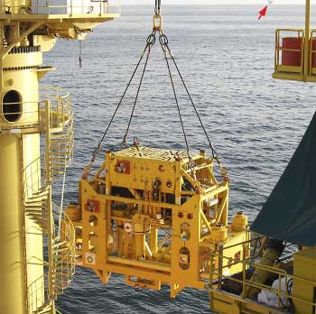
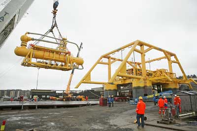
MultiBooster. After successful installation in Lyell Field offshore UK, Aker Kvaerner’s MultiBooster subsea boosting system is now being applied in the deepwater Gulf of Mexico. Two pumps became operational in BP’s King Field in December 2007 at about 5,500 ft of water depth, making it the deepest MPP application to date. The MPPs also set a record for longest stepout, being more than 18 mi from the Marlin production platform, Fig. 1. BP expects the boosting system to increase the field’s production by 20% and extend its life five years.
 |
|
Fig. 1. Two of Aker Kvaerner’s twin-screw multiphase pumps, called the MultiBooster, were installed in BP’s King Field in late 2007. The pumps will send well fluids 18 mi to the Marlin production platform, visible at the upper right. Courtesy of Aker Kvaerner.
|
|
Each unit uses a Borneman twin-screw pump with a 68,000-bpd capacity, rated to 5,000 psi. The system is designed to handle high gas content. The pilot unit at Lyell Field, for CNR International, was installed in January 2006 at a water depth of about 500 ft.
Baker Hughes multiphase ESP. In the summer of 2007, Baker Hughes Centrilift placed seven subsea multiphase Electric Submersible Pumps (ESPs) in Petrobras’s Espadarte and Golfinho Fields offshore Brazil, in 4,600 and 4,800 ft of water, respectively. The installations at Espadarte are expected to lift an average of 19,000 bpd per well, and those at Golfinho, 28,000 bpd per well.
Baker Hughes Centrilift will also install two multiphase ESP vertical booster stations as part of the first phase of Shell’s planned BC-10 subsea production project offshore Brazil. Additionally, four ESP vertical booster stations, not specifically multiphase but able to tolerate some gas, will be supplied by Baker Hughes Centrilift to operate in conjunction with FMC Technologies liquid/gas separators at BC-10. The project will be the first development designed, from the start, for subsea production.
Five of these non-multiphase subsea ESPs, along with FMC liquid/gas separators, will also be used in Shell’s Perdido development in the GOM. First oil is expected for both developments around 2010. Another unit began pumping to a Petrobras FPSO in Jubarte Field, offshore Brazil, in July 2007. It is producing about 22,000 bpd in 4,600 ft of water, and eight additional units are planned in the upcoming months.
Horizontal ESPs in the GOM. FMC Technologies was awarded a contract to supply deepwater subsea systems to Petrobras for the Cascade and Chinook development in the deepwater Gulf of Mexico. FMC will supply two subsea horizontal ESPs, a new technology in the GOM, along with four horizontal subsea trees, three manifolds and control systems, starting in fourth quarter 2008. The pumps will operate at a water depth of about 8,500 ft.
Camforce Boosting. A joint venture of Cameron, Curtiss-Wright EMD and Leistritz has developed a subsea MPP system. Camforce Boosting refines a pump originally developed by the latter two companies and Petrobras: the twin-screw SBMS-500.
The new pump has an increased design depth of operation and shut-in pressure: 6,560 ft and 5,000 psi from the SBMS-500’s 3,280 ft and 1,740 psi. At the same time, the pump’s capacity to deliver differential pressure increased to 1,450 psi from 960 psi, while its size and weight were reduced.
Cameron is in discussions with several operators to install the pump, but says the industry appears to be waiting to see how other systems perform. The company envisions its booster as part of a full subsea process offering including its 30,000-bpd subsea liquid/gas separator, in development with Curtiss-Wright EMD (rated to 10,000 ft of water depth and 10,000-psi shut-in pressure), and the subsea production-enabling MARS unit (discussed below), as well as multiphase metering, compression, desanding and injection.
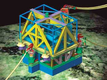
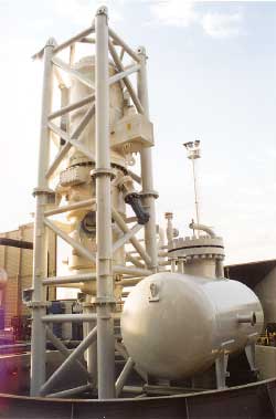
SBMS-500. The Petrobras MPP was initially scheduled to start operations in Marlim Field in November 2005, but it was damaged during installation, and the project was postponed while the pump underwent design improvements. The redesigned pump can operate in water depths up to 3,280 ft and is rated to 3,000 psi of shut-in pressure. Its final integration and testing will conclude in March 2008, and a pilot installation is planned as soon as the next installation vessel is available, Fig. 2. The pump is designed to operate for two years without maintenance.
 |
|
Fig. 2. Petrobras hit a few bumps in the road on its way to deploy the SBMS-500, but the multiphase pump is redesigned and planned for installation in Marlim Field in mid-2008. Courtesy of Petrobras.
|
|
There are two candidate wells for the pump in Marlim Field, both of which produce to the P-20 platform from a water depth of about 2,100 ft. Power to the 1.3-MW pump will be generated at P-20 and transmitted by cable. Control will be hydraulic/electric, and monitoring data will be transmitted by electric and optical lines. The pump is expected to increase liquid production from the well by 60%.
SUBSEA SEPARATION
Subsea separation is both a costly and a highly risky technology to implement, which may account for its slow rate of adoption compared with subsea boosting. The technology is risky because separators tend to require regular cleaning and adjustment, and subsea equipment must by definition operate without maintenance for years.
However, separating water on the seafloor can offer substantial advantages, including increased production drive, decreased flow assurance issues in risers and smaller requirements of expensive topside real estate for processing. These factors have led to recent growth in the development of subsea separation projects, often deployed in conjunction with subsea boosters and other components.
Troll Field. The longest-operating subsea separation system is the SUBSIS (SUBsea Separation and Injection System) developed by ABB for Norsk Hydro’s Troll Field. The 400-ton module, measuring 56 ft long and wide and 20 ft tall, has been operating in 1,100 ft of water depth since 2000. It is a simple, gravity-based oil/water separator with a reinjection system for the produced water.
Oil is produced to the Troll C platform 4 km away. In its first year, the Troll module handled an average of 20,000 bpd of fluids. By freeing up space on the platform, it allowed production of an additional 2.5 million bbl of oil.
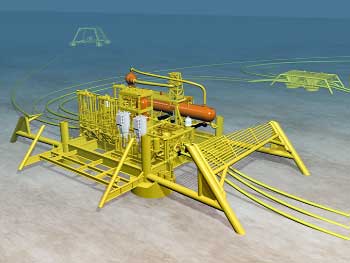
VASPS. The Vertical Annular Separation and Pumping System (VASPS) developed by Petrobras is another operating subsea system. A prototype was installed at a water depth of 1,150 ft in Marimba Field, offshore Brazil, in July 2001 by a joint industry project involving Petrobras, ExxonMobil and AGIP. The separation unit takes production from Well MA-1-RJS, 1,800 ft away, and the stream travels 3,400 ft from the VASPS to the P-8 platform.
The VASPS separates gas from liquid by passing the stream through a helical channel, and then allows the gas to reach the platform under its own power while an ESP lifts the liquid, Fig. 3. At Marimba, a failure in the ESP forced bypass of the VASPS after only four months of operation, but a successful rig intervention to replace the pump in January 2004 brought the separation system back online, and it has operated successfully ever since. The flowrate from the well has increased to an average of 6,300 bpd from 4,700 bpd before installation, and Petrobras was able to discontinue gas injection of 3.5 MMcfd to the reservoir.
 |
|
Fig. 3. Petrobras’s Vertical Annular Separation and Pumping System (VASPS) passes well fluids through a helical channel to separate gas from liquid. An ESP then pumps the liquid to production facilities.
|
|
Design improvements are underway to add oil/water separation capability, as part of the company’s PROCAP 3000 program to improve deepwater production in the Campos Basin. The VASPS will likely be used in the basin’s North Asset to allow demobilization of a floating unit and production to a remote existing facility. It may also allow the addition of two more small fields to the system.
FULL SUBSEA PRODUCTION
The most complex subsea production system installed to date is the Tordis Field enhanced oil recovery project in the North Sea, developed by FMC Technologies and StatoilHydro. The subsea development, which is due to come on stream soon at a water depth of 650 ft, comprises gas/liquid and oil/water separation, desanding, reinjection and multiphase boosting to the Gullfaks C platform 7 mi away.
The motivation for developing a full subsea EOR project is the increasing watercut at the mature Tordis Field, which produced too much water for the platform to separate economically. By moving these operations to the seafloor and reducing the wellhead pressure, Statoil expects to increase Tordis’s recovery factor to 55% from 49%, adding an additional 15-17 years to the field’s life and allowing recovery of an additional 35 million bbl. In addition to rising watercut, high sand production has been a major EOR challenge.
The Tordis development comprises five satellite wells and a four-slot production template connected to a manifold from which two 10-in. pipelines flow to Gullfaks C. The integrated Subsea Separation, Boosting and Injection (SSBI) station, contained in a single frame with modular design for individual component retrieval, is located near the manifold, Fig. 4.
 |
|
Fig. 4. Cutaway of the Tordis Field subsea installation for StatoilHydro showing the components of the Subsea Separation, Boosting and Injection (SSBI) station. Courtesy of FMC Technologies.
|
|
Well fluids enter an inlet cyclone, where gas is routed to a bypass pipe while water, oil and sand enter the gravity-based horizontal separator, Fig. 5. Separated oil, possibly with some remaining water, is recombined with the gas stream and sent to the 2.3-MW, helico-axial MPP and boosted to the pipelines.
 |
|
Fig. 5. The SSBI’s separation component is seen being placed inside the subsea station’s protective frame for installation at Tordis Field. Courtesy of FMC Technologies.
|
|
Sand and water are removed from the separator as a batch process once or twice a week, and sent to a simple gravity-based desander. The water is then sent to a 2.3-MW, centrifugal water injection pump located above the manifold, and injected via a disposal well into the Utsira reservoir. Sand from the desander enters the disposal well downstream of the water injection pump. The sand-handling system is designed so the pumps only see a small fraction of produced sand, to extend the time between maintenance events. Both pumps were designed and built by Framo Engineering.
Power is fed to the SSBI station via a high-power umbilical, and the controllers and variable-speed drives that determine the pumps’ speeds are on the platform. To provide stable well conditions, pressure in the separator is controlled by adjusting the MPP speed, and the level of the oil/water interface is controlled by adjusting the water injection pump speed. The liquid level in the separator is self-regulated with an overflow drain.
SUBSEA COMPRESSION
Subsea gas compression offers the possibility of making stranded gas fields profitable by boosting pressure to pipelines without the investment and operational costs of platforms. It is being considered for the giant Ormen Lange gas field, about 75 mi offshore Norway in 2,800-3,600 ft of water. Gas production from Ormen Lange to land-based processing facilities at Nyhamna, Norway, began in September 2007. From Nyhamna, gas will be sent to the UK via the 750-mi Langeled pipeline, the longest in the world. At full production, the project is expected to meet 20% of the UK’s gas needs.
To maintain the production plateau and extend the economic life of the Hydro-operated field, offshore compression will be required. Without compression, production is expected to decline rapidly by 2015 and to cease altogether by 2029; compression could extend production to 2035.
Two alternatives are being considered: 1) platform compression; and 2) a subsea compressor station developed by Aker Kvaerner with a GE Oil & Gas integral compressor-motor unit. The subsea compressor unit, called BLUE-C, is a vertical centrifugal compressor driven by a 12.5-MW gas-filled Converteam electric motor, Fig. 6.
 |
|
Fig. 6. GE’s BLUE-C is a vertical centrifugal compressor driven by an electric motor. Courtesy of GE Oil & Gas.
|
|
The full subsea package will consist of four identical compressor trains, each consisting of:
- An Aker Kvaerner vertical separator to remove water and solids and demist the gas
- A BLUE-C compressor unit
- A 400-kW Aker Kvaerner subsea pump
- Converteam variable-speed drives for the compressor and pump
- Power supply and circuit breaker modules from Converteam.
Each of the four compression trains will handle one-fourth of the full production. If selected, the subsea system will be placed at a water depth of 2,800 ft and will cover an area 230 ft by 175 ft, with a height of 85 ft. The system uses active magnetic bearings for a simple and oil-free design.
The compression package will be powered and controlled from shore, 75 mi away, via high-voltage cables. Avoiding electrical losses over this distance will prove one of the biggest design challenges.
A completely integrated unit is expected by 2009, after which it will undergo two years of full-load endurance tests. Hydro plans on a final decision of offshore compression concept by 2011 and installation by 2015.
SUBSEA SYSTEM ENABLER
One barrier to installing subsea production equipment in existing developments is the traditionally high risk and high cost of installation, which may require field shutdown, new hardware foundation and pipeline de- and re-commissioning, as well as dangerous diver operations. The Multiple Application Reinjection System (MARS) developed by DES Operations Ltd., now owned by Cameron, seeks to eliminate these problems by acting as a universal interface (or “USB port” as the company’s promotional literature puts it) for subsea (or topside) trees.
MARS allows any production equipment to be retrofitted between existing Christmas tree isolation barriers, eliminating the need for expensive, high-risk disruptions of field infrastructure. The system introduces a coaxial flowpath insert into the top of the Christmas tree or the choke body to allow the well fluids to flow to an external flowloop for application of a process technology, such as boosting, metering, dehydration or chemical injection. The flow is then returned through the tree and back into the existing infrastructure.
The first field application for MARS was BP’s King Field, where two units were used for the installation of the Aker Kvaerner multiphase pumps. The hardware will also be used by Shell for subsea well stimulation in Bittern Field, in the North Sea. Two MARS units will be fitted to existing subsea trees in Bittern, while a third will be installed on a new tree onshore before deployment to the field.
ALL-ELECTRIC PRODUCTION
Another innovative Cameron technology is the all-electric CameronDC Subsea Production System, Fig. 7. As part of a technology cooperation agreement signed by Total and Cameron in January 2004, Total conducted extensive technical and economic reviews of the hardware to verify advantages over electro-hydraulic technologies. Chief among these advantages are a 2.5% increase in (uptime) availability over conventional systems. Other advantages include:
- No batteries, no hydraulics and no accumulators
- Electrically actuated production gate valves
- Electrically actuated annulus gate valves
- Electrically actuated, subsea-retrievable choke
- Electrically actuated chemical injection valves
- Better environmental performance (no hydraulic supply in the umbilical, and no subsea accumulators)
- Lower umbilical costs, especially for long stepouts.
 |
|
Fig. 7. The all-electric CameronDC Subsea Production System offers a 2.5% increase in (uptime) availability over conventional electric-hydraulic systems, as well as better environmental performance and lower umbilical costs. Courtesy of Cameron.
|
|
In addition, the subsea control module is electric, as well as the power regulation and communication module.
The system was first unveiled at the 2004 Offshore Technology Conference. It was field tested in 2003 for 22 days in 50 ft of water at Cameron’s Stavanger facility, and again in 2004 for six months at BP’s Magnus platform in 600 ft of water. The production system configuration is essentially an all-electric subsea tree comprising actuated valves, and choke(s). Total E&P Nederland B.V. will use the system on its K5F multi-well development in the North Sea. The control system is configured for expansion to four wells, but only two are planned for K5F. Total tentatively plans to drill and complete two wells at K5F in succession, suspending one. However, the economics of that has not been settled as of this writing, so each system may be installed immediately after each well is drilled. Preliminary deployment has begun and is scheduled to be completed sometime near the end of first quarter 2008.
Except for the all-electric feature, the actuators function in a similar fashion to that of hydraulic actuators. They are spring driven to return to their non-energized position when de-energized. Typically, the actuators will require 500-3,000 watts to open, depending on its size, bore pressure, temperature and other variables. To maintain its energized position requires only 20-100 watts.
The variable choke is motorized/gear-driven with an ordinary wheel that can be turned by an ROV. To eliminate a penetration point and increase reliability, it was decided to eliminate the “tattletale” stem indicator that, on most conventional systems, shows the open or closed status of the valve when viewed by an ROV. Instead, a pair of digital sensors indicates the valve position via electrical signal to the surface.
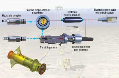
Chemical Injection Metering Valve. An optional upgrade to the electric (or an electric-hydraulic) production system is Cameron’s new chemical injection valve, which the company says is an answer to a technology gap where more precise chemical metering is needed, such as with low-dose inhibitors. The Chemical Injection Metering Valve (CIMV) may be used separately or as an add-on to the system. It is essentially a large, electric needle valve that has a positive displacement disk element that rotates once for every unit of liquid that is injected, Fig. 8. Each rotation sends an electrical pulse to the surface to allow precise metering of injected chemicals, accurate to within 2%. The valve is ROV retrievable and can control flow as low as 0.2 L/hr. There are high-volume and low-volume versions. Total has ordered one on its Kessog development in the central North Sea.
 |
|
Fig. 8. Diagram showing the operating principles of the Chemical Injection Metering Valve (CIMV). Courtesy of Cameron.
|
|
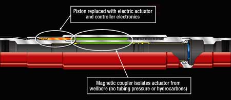
All-electric SCSSV. Halliburton has developed a new type of Surface-Controlled Subsurface Safety Valve (SCSSV) that complements CameronDC, although it will not be installed at K5. The thinking is that, as long as they were eliminating hydraulics, why not incorporate an all-electric SCSSV as well? The Halliburton safety valve is not only all electric, but it also has no mechanical link to the valve itself. Instead, it has a permanent magnet in a sliding holder that sits on the outside of the tubing, away from contact with well fluids. When driven by an electric motor, it magnetically pulls on the SCSSV to flip it open or shut, Fig. 9. This eliminates a source of mechanical failure as well as potential pressure leaks to the annulus and the control line.
 |
|
Fig. 9. A new electric SCSSV uses a magnet in a sliding holder outside the tubing to pull the valve open or shut. Courtesy of Cameron.
|
|
The body of the valve is made of high-nickel, non-ferrous metal to prevent interference with the moving magnet. It is rated to 10,000 psi and 257°F, and will be available for up to 5½-in. tubing. It is designed to use 25-30 W to open, and 10 W to hold open. The valve will be under development and testing though most of 2008, with a field trial planned for late in the year.
CONCLUSION
While many technical and economic hurdles must still be overcome to make subsea production systems a mainstream technology, the last year has seen unprecedented growth of pumps, separators and other equipment on the seafloor. The introduction of the MARS system stands to substantially lower the risk and cost of installing such equipment in existing and future deepwater developments. Projects like BP’s King Field and Statoil’s Tordis Field offer the prospect of moving the entire production platform onto the seafloor. Offshore operators will be watching these projects carefully over the next year to determine the shape of their own deepwater prospects. 
|

