The pump successfully added production and made available new gas reserves from existing wellbores in a group of Devon wells in central Alberta.
Darrell Eagles, Devon Energy; and Farhan Farshori, Global Energy Services
Devon Canada required an artificial lift system suited for low-rate dewatering that would work effectively in low-pressure and low-permeability reservoirs. A group of wells in the company’s central Alberta assets had been shut in for several years due to liquid loading. They required a dewatering device that would continue to operate in a pumped-off state. Given the production rates and gas prices at the time, many typical dewatering solutions were not economically viable. Devon installed a unique hydraulic pump to dewater these wells, resulting in steady increases of gas rate and decreases of water rate.
BACKGROUND
Devon’s central development region, encompassing Alberta’s central and southern plains, produces crude oil, gas and natural gas liquids from multiple formations.
Production optimization from conventional and unconventional gas wells has been a focus of the central region’s production engineers. To optimize production, Devon engineers target new and mature gas wells that they believe are not producing gas to their optimal capacity. These are typically shut-in wells, suspended wells, marginal producing wells and liquid-loaded wells. A recent study by the Petroleum Technology Alliance Canada estimates that 1-8 Tcf of recoverable gas is left in place in conventional gas reservoirs in the Western Canadian Sedimentary Basin (WCSB).
Devon identified a group of wells in close proximity to one another that initially appeared to have loaded up with formation water. The vast majority of these wells had been shut in for years, and the likely next step in the wells’ life was abandonment, as there were no other uphole zones to target. A pressure survey was conducted throughout the pool, and many of the wells were found to have significant reservoir pressures-in some cases higher than the estimated average pool pressure. A detailed engineering review concluded that the wells had loaded up due to insufficient energy to lift the formation fluids up the production tubing. A re-fracturing program was conducted in 1999 and 2000 to help optimize the inflow from the wells, but many of them encountered underlying water and could not establish any inflow. Several of the wells had produced with a velocity string, and a few plunger lifts had been attempted with limited success. Many of the wells were also on a soaping program to help lighten the hydrostatic head pressure to maintain inflow. The entire gathering system operated at very low pipeline pressures, so there was no opportunity for wellhead compression. To produce these wells, artificial lift would be required.
Given low gas prices at the beginning of the program, certain dewatering solutions were not economically viable. The challenge was to find a low-cost dewatering pump that would be adaptable enough to be installed at various depths, in various pressure, temperature and fluid environments. It had to be able to pump a variety of fluids, with some solids, at varying rates. Finally, it had to be durable enough to function in the well for long periods with minimal maintenance.
DEWATERING OPTIONS
Devon has used or considered many of the standard options for dewatering in its central region, including stop-clocking, swabbing, soap injection, using coiled tubing as a velocity string, plunger lift and gas lift. These options are not appropriate for all wells in the region; most do not allow 24-hr gas production, which limits the daily production volumes achievable. Also, since these solutions require energy and pressure from the reservoir, they cease to provide benefit as the reservoir pressure decreases over time; consequently, they are only temporary solutions.
Gas lift is capital intensive, requiring nearby compression and in some cases complex downhole equipment. Gas lift systems artificially increase BottomHole Pressure (BHP) and cannot ultimately recover at low BHP.
Many of the target wells do not have enough BHP to lift or assist in gas lift; consequently, solutions such as soap, plunger lift, coiled tubing string, gas lift and swabbing are not appropriate.
Wellhead compression increases gas velocity and decreases surface line pressure; however, it can be capital intensive, introduces higher operational costs, and is also a temporary solution.
Downhole pumps are probably the best solution for production optimization, as they can effectively dewater low-pressure wells for a long period. The challenge is to choose a suitable downhole pump.
Rod pumps are prone to rod and tubing wear in deviated or horizontal wells, and to gas locking in low-pressure wells. Progressive Cavity Pumps (PCPs) are also prone to rod and tubing wear, and are prone to premature wear if the pump is run dry or devoid of water in wells with low fluid rates.
The Activator Hydraulic Submersible Pump (HSP) was chosen to address the dewatering challenges and optimize production in some of Devon’s central Albertan gas wells.
Artificial lift using a downhole pump was needed. Pump-jack/rod-pump systems and Progressive Cavity Pumps (PCPs) were rejected because:
- Installation and component costs were higher than for the hydraulic pump.
- Rod pumps and PCPs were likely to cause rod and tubing wear in deviated and horizontal wells.
- Mechanical wear was likely when pumping 100% water.
- There was a fear of running dry and wearing out the downhole components.
- Rod pumps are prone to gas locking in low-pressure wells.
- PCPs are prone to premature wear if the pump is run dry in wells with low fluid rates.
- Pump-jack/rod-pump systems have poor portability compared with the hydraulic system.
The primary reasons Devon chose the hydraulic pump are discussed below.
Gas lock prevention. Gas locking occurs when the maximum pressure developed within the pump chamber is less than the pressure required to open the pump discharge valves. The pressure in the chamber is a function of the inlet pressure and of the ratio of the suction volume to the discharge volume, called the Compression Ratio (CR). These terms are related by the thermodynamic law of compression under adiabatic and isentropic conditions, which can be stated as:
where V1 is the volume in the piston chamber at the end of the intake stroke; V2 is the volume occupied by the compressed gas at the end of the production stroke (i.e., the “unswept volume”); P1 is the pressure of the gas when admitted into the chamber; and P2 is the pressure of compressed gas at the end of the production stroke. The exponent k is the ratio of the specific heats of the gas, cp/cv. For natural gas, this ratio tends to be about 1.29.
The 1-gal/stroke (3.8-L/stroke) hydraulic pump has a V1 of 1.0 gal (3.8 L) or 232 in.3 (3,801 cm3) and a V2 of 1.8 in.3 (29.5 cm3), so the volume term works out to a compression ratio of over 500. When P2 exceeds the hydrostatic pressure in the coiled tubing plus any static pressure on the outside of the tubing, the discharge valves will open. This is the normal result in all but the lowest achievable flowing BHPs.
If liquid is present at the hydraulic pump’s suction, it will be pumped. If gas is present, it will be compressed. Gas locking is possible, but with the pump able to develop a CR of over 500, it would only occur if there was a very low suction pressure or a very high discharge pressure. At 5,250 ft (1,600 m) and 100 psig (690 kPa) flowing tubing pressure, the flowing BHP would have to be less than 5 psia (34 kPa) for a gas lock.
The pump’s high CR allows it to avoid gas locking even when it is landed above the perforations, where it is subject to much greater gas interference. The pump can be landed above the perforations if there is no collar or if a bridge plug is used just below the perforations.
Devon is focused on maximizing gas extraction. As bottomhole reservoir pressure decreases, the hydraulic pump will demonstrate superior longevity compared with other artificial lift options because of its ability to operate at very low BHP without gas locking.
Low-pressure operations. Dewatering low-pressure, low-liquid-volume gas wells with conventional oilfield technology requires that the well satisfy the pump’s minimum Net Positive Suction Head (NPSH) requirement. For a conventional rod pump, the NPSH requirement is on the order of 100 ft (30.5 m) of liquid above the pump, which adds over 40 psig (275 kPa) of backpressure to the formation. Failure to provide the minimum NPSH to a rod pump results in the traveling valve failing to open, and trapped gas in the pump barrel being compressed by the plunger falling. If the gas compression is inadequate to open the traveling valve, then the plunger simply moves up and down without pumping any liquid. This condition continues until either a) leakage past the plunger adds enough mass to the fluids in the barrel to lift the traveling valve or b) the flowing BHP increases enough to open the standing valve. It can take several days on some wells to break a gas lock in a rod pump.
A dynamic pump such as an Electric Submersible Pump (ESP) or a jet pump can require five to six times as much NPSH as a conventional rod pump. Failure to provide this higher NPSH can cause a dynamic pump to cavitate. Cavitation is the formation and subsequent collapse of steam bubbles in a liquid stream. The bubbles form in the low-pressure part of the pump (in the eye of the impeller on an ESP or the opening of the throat in a jet pump) and then collapse as the pressure rises. When the bubbles collapse, the surrounding liquid rushes into the void at very high speed, which can tear metal from the pump’s control surfaces and destroy the pump’s ability to move liquid.
As discussed above, the hydraulic pump is designed to retain a very small unswept volume of fluid within the pump chamber, to prevent gas locking and allow it to pump 100% liquid, 100% gas, or a mixture of gas and liquid. In very deep wells (i.e., with a large hydrostatic head of produced water) with very low flowing BHP, well conditions can prevent the pump’s discharge valves from opening for a brief time.However, a small change in BHP changes the compression dynamics and allows the pump to develop a high enough compression ratio to restart pumping within a few strokes.
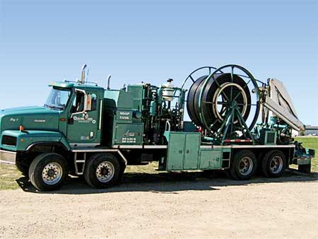
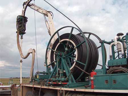
Portability. The hydraulic pump is easily installed, removed and re-installed. It runs on three carbon steel coiled tubing lines-two hydraulic entry lines and one production exit line-or four coiled tubing lines if chemical injection or downhole sensing equipment is required.
Installation requires a coiled tubing unit and a trailer with two spools for the hydraulic lines, Fig. 1. The pump and tubing strings are deployed simultaneously in a well’s production casing. Depending on depths, the entire system can be removed, installed in another well and functional within a day, taking into account all service utilities.
 |
|
Fig. 1. Installation of the hydraulic pump requires a coiled tubing unit and a trailer with two spools for the hydraulic lines.
|
|
To remove the pump, the encapsulated lines are spooled onto the coiled tubing unit spool and the surface unit is loaded into a trailer. Then the pump is disconnected and the well is capped.
The surface equipment is entirely self-contained; there are no building pads to lay and no pump assembly is required. The pump can be set up by making four fittings and two fluid connections. In one case, the pump was pulled out of one unsuccessful well (Provost 10-7) at 7 a.m. and was running in a new well (Provost 6-31) by 4:30 p.m. the same day.
The benefits of the portability of the system are significant. Installing, removing and re-deploying the system are quicker and potentially cheaper than for other pumping systems such as PCPs and rod pumps, which require a service rig. Also, the system’s portability allows Devon to test the production upside from dewatering gas wells. Using the hydraulic pump, Devon has designed a well testing program in which well candidates are selected for dewatering; if the dewatering does not result in viable production upside, the pump is simply moved to the next well candidate. A major portion of the project costs for water lifting from gas wells are tangible (equipment) costs, so redeploying an existing unit to a new location is very inexpensive.
Determinability of pumped-off state. The hydraulic pressure measured at the surface is a good indicator of the mix of liquid and gas within the hydraulic pump. For example, if a pump is taking in 50% liquid and 50% gas by volume at flowing bottomhole conditions, then as the plunger moves toward the discharge valves the gas will be compressed until the pressure within the pump exceeds the required discharge pressure. As the pump pressure approaches the required discharge pressure, the hydraulic pressure will increase until it exceeds the discharge pressure. This discharge pressure is a clear indication of the amount of water in the coiled tubing above the pump; i.e., the hydrostatic head. The amount of time that the hydraulic pressure maintains the minimum value indicates the mix of liquid and gas entering the pump.
Automation can be applied to speed the pump up or slow it down in response to the duration of the minimum pressure and the magnitude of the maximum pressure. The pump-off control algorithm can be adapted to the needs of each well to maximize its production.
Filtering of frac and formation sand. The pump is fitted with a 10-slot, self-flushing sand screen over its intake ports, to filter large particles of fracture sand proppant, formation sand, coal, debris and cement. The sand screen is a 4.2-ft (1.3-m) tube with a 1.5-in. (3.8-cm) outer diameter and 0.01-in. (0.254-mm) spiral slots. To assist in the filtering large particles, the fluid exhausted from the pump’s cooling chamber back-flushes the screen with each stroke. Particles smaller than 0.01 in. (0.254 mm) in diameter that enter the pump are pumped.
Suitability for deviated or horizontal wells. Rod pumps and progressive cavity pumps are powered by moving rods connected to the surface. In highly deviated wells and in some horizontal wells, these rods can rub against the tubing wall along the deviated section, causing rod or tubing wear and thus reducing the pump’s run life.
In contrast, the hydraulic pump is operated by hydraulic fluid injected from the surface, so there are no moving parts within the deployment tubing. Thus the hydraulic pump avoids this source of wear in deviated and horizontal wells, making it better suited for this type of deployment.
Ease of operation. The hydraulic pump’s clamshell-hooded surface unit is easy to use and to maintain. The entire enclosure opens so that all mechanical components are within reach. There is no access panel. It is compact, quiet and easily serviced. The pump rate can be manipulated from the surface unit using a flow divider that almost instantly adjusts the rate within a range of 0.5 to 150 bpd.
The flow of hydraulic fluid to the downhole pump dictates the cycles of the pump, while the speed with which the fluid is sent dictates the frequency of each cycle. A single joystick in the surface unit determines the amount of hydraulic fluid sent to the downhole pump, thus controlling the frequency and volume of the pumping cycles.
Year-round dewatering. From a field operations perspective, the surface hydraulic driver provides heat tracing to allow production of formation water without the risk of freezing in the winter. The hydraulic lines that connect to the wellhead can be spliced and wrapped around the wellhead and associated piping. The hydraulic fluid provides enough heat to keep everything in operation through even the coldest days.
HOW IT WORKS
The pump is a positive-displacement, double-acting piston pump driven from the surface by hydraulic pressure applied through coiled tubing. The pump is more reminiscent of compressor technology than typical downhole pump technology in that it is driven on both the upstroke and the downstroke, and it has robust suction and discharge valves designed to operate in conditions ranging from 100% gas to 100% liquid, Fig. 2.
 |
|
Fig. 2. Schematic of the hydraulic pump showing upstroke and downstroke.
|
|
Reciprocating compressors are notorious for being intolerant of liquid slugs; this is due to the very high piston speeds in a reciprocating compressor, often in excess of 10 ft/s (3 m/s). These high speeds tend to cause a liquid slug to raise cylinder pressure faster than the discharge valves can relieve it, and consequently damage the compressor through overpressure. The hydraulic pump runs much more slowly, with speeds in the 0.1-ft/s (.03-m/s) range, so the valves can accommodate the rate of pressure change. This slow speed, in combination with robust valves, allows the pump to handle high iron content, sludge, contaminants, sand and other particles.
The surface-drive system can be powered by electricity, natural gas or propane, and a variable-speed plan can be implemented with mainstream drive technology. The pump can be adjusted at the surface to accommodate changing water volumes from the well. This compatibility with pump-off control schemes significantly improves its longevity.
RESULTS
Devon tested the hydraulic pump in nine gas wells in the company’s central development region, in Alberta’s south and central plains. All of the test wells were located within about a 10-mi radius, to facilitate the transfer of equipment between locations, mitigate risk and reduce testing costs. Four of the wells-Provost 6-31, Gadsby 5-4, Provost 9-20 and Leahurst 16-30-had successful pump installations and have remained in active service. The remaining five wells were unsuccessful and are awaiting abandonment or recompletion into another zone. Where the installation was not successful, the pump was removed from the well and subsequently moved into another candidate location. Devon currently has one hydraulic pump in stock from an unsuccessful location that is being targeted for a stalled coalbed methane well in the central region.
Discussed here are results from two successful installations in gas wells producing from the Cretaceous Viking Formation in central Alberta, both of which had previously ceased production due to liquid loading.
The Provost 6-31 well, completed in 1975, produced 2.2 Bcf before loading up in January 1996. A few attempts were made to optimize the well, including the installation of a velocity string to maintain critical flow. This was successful until early 2000, when the well loaded up for a second time. In 2002 and 2004, soap injection along with the velocity string was attempted unsuccessfully to help lighten the formation fluids. In 2005, the well was hydraulically fractured to help increase inflow. The fracture treatment encountered underlying water and rendered the well unable to flow. Reservoir pressure was insufficient to carry the water to surface, Fig. 3.
 |
|
Fig. 3. Production history of the Provost 6-31 well.
|
|
In April 2006, the pump was installed in the Provost 6-31 well to implement artificial lift and test the functionality and durability of the system. After an immediate jump in both gas and water rates, gas production continued to climb rapidly in the first three months of dewatering, while water production declined sharply and then tapered off to less than 10 bpd, Fig. 4.
 |
|
Fig. 4. Installation of the hydraulic pump successfully dewatered the Provost 6-31 well and restored production to historical rates.
|
|
The installation successfully restored production to historical rates. After more than 2 yr in service, the pump continues to run effectively, and the gas rate is averaging about 150 Mcfd with no sign of decline. Since the installation, Provost 6-31’s proved reserves have been adjusted up 500 MMcf to 2.7 Bcf from 2.2 Bcf, representing a little more than 20% additional ultimate recovery from a well that, before the installation, was considered incapable of producing.
A subsequent installation was completed in January 2007 after re-completing a suspended well, Gadsby 5-4, into an uphole zone. The well had first came on production in 1993 from the glauconitic zone. The well produced at a high rate of 6 MMcfd, but quickly watered out. Plunger lift was attempted in 1996, but was only successful for about two months. Dewatering the glauconitic zone was expected to result in such large produced water volumes that water handling would become cost prohibitive. It was decided to target the uphole zone instead.
The upper zone initially produced 50 Mcfd of gas, but this lasted only a few days before the well succumbed to severe liquid loading requiring immediate artificial lift. The hydraulic pump was installed, yielding an immediate increase in gas rate and decrease in water rate from an initial rate of 40 bwpd. The system has been running effectively for over 1 yr.
This installation is pumping significantly more formation water than Provost 6-31, about 22 bpd. Added production from Gadsby 5-4 due to the pump installation has added about 250 MMcf to the well’s recoverable reserves.
Without the dewatering pump, the Gadsby 5-4’s recompleted upper zone might have been abandoned during the initial completion due to the well’s inability to flow. The successful pump installation provides an economic scenario for future use of this type of recompletion in wells whose initial test rates are uneconomic and whose true rates are masked by liquid loading.
These two cases illustrate the potential latent in existing wellbores that are either shut in or abandoned. The pump successfully added production and made available new reserves from existing wellbores. There are many of these wells in the WCSB. A majority of these wells are in mature areas with a lot of infrastructure already in place. Being able to install a portable pumping system into wells surrounded by gas-gathering systems, compressor stations and processing facilities that are already in place would greatly reduce the capital exposure and risk of implementing such projects.
COMPLICATIONS
A number of challenges needed to be resolved to allow efficient operation of the hydraulic pump in the well.
Corrosion. In one of the Devon wells, Leahurst 16-30, the pump’s coiled tubing deployment string experienced corrosion from carbon dioxide within 6 mo of deployment. The coiled tubing string was of a carbon steel composition that is common throughout the industry, and the corrosive environment was judged likely to affect some, but not all, other pump deployments in Devon’s gas wells in the area. Devon deployed a chemical inhibition program to resolve the CO2 corrosion problem with reasonable success.
With these concerns in mind, Global Energy Services has introduced a new deployment system that uses multiple corrosion-resistant metal tubulars of various compositions in a single deployment string encapsulated by high-density polyethylene, low-density polyethylene and thermoplastic vulcanizate (i.e., elastomer) plastics, Fig. 5. The combination of corrosion-resistant metals and tailored plastic encapsulation is designed to provide superior chemical and corrosion resistance. This type of conveyance, combined with a small inhibition program, should effectively deal with the potential corrosion problem.
 |
|
Fig. 5. A new deployment system uses three or four metal tubulars encapsulated by various polyethylene and thermoplastic vulcanizate plastics to simplify pump deployment and prevent corrosion.
|
|
The new deployment system has been used to dewater six wells since its introduction in mid-July 2008. Devon plans to use it with the hydraulic pump in a 6,000-ft horizontal gas well in East Texas in August 2008.
Installation complexity. This new all-in-one deployment string also addresses a second complication in deployment of the hydraulic pump: the complexity and cost of deploying the three (or four, if injection is necessary) separate coiled tubing strings. The current installation method, though quick and efficient, requires a coiled tubing unit and a trailer with two spools for the hydraulic lines. The new, single deployment string with the three or four internal tubes will require only one coiled tubing unit on location and fewer installation personnel, resulting in lower costs and quicker installation times.
Wellhead and annular bag complexity. A specialized wellhead, called the triple hanger, is currently used to hang the pump and accommodate the three separate coiled tubing strings. The new encapsulated configuration requires a slightly modified standard wellhead and BOP, thus simplifying and reducing the cost of the wellhead configuration. The modifications accommodate the encapsulated tubing and provide increased safety at the wellhead.
User-friendliness of alternate driver. Support staff and field operator acceptance of a new product is essential to its success. Given its ease of use and functionality, the hydraulic pump was very popular with the Devon operators.
In 2006, a cheaper and higher-maintenance surface driver for the pump was tested on two wells, Provost 9-20 and Gadsby 5-36. The operators rejected the new driver, whose smaller, single-cylinder, 10-hp engine burned more oil than the previous surface driver and frequently fouled spark plugs, requiring more maintenance.
FUTURE APPLICATIONS
Given the hydraulic pump’s success in Devon’s gas wells with landing depths ranging from 800 to 4,100 ft, the next step for the pump will be deployment in deeper wells.
Devon plans an installation of the hydraulic pump in a deep gas well with a landing depth of 11,150 ft (3,400 m) during the summer of 2008. The hydraulic pump was chosen because it offered a cheaper solution than conventional rod pumping and because of its reliability in the previous Devon applications.
Devon also plans to deploy the pump in a horizontal gas well in the Jean Marie Formation of North East British Colombia. Typical TVDs of these wells are around 4,600-5,600 ft (1,400-1,700 m). The pump will be landed into the heel or lateral of the horizontal leg. Another major gas producer has shown a very strong production increase after deploying the hydraulic pump in its Jean Marie Formation well. 
.
|
THE AUTHORS
|
|
|
Darrell Eagles is a production engineer with Devon Canada in the company’s central development region in Alberta, working in deep, tight conventional and unconventional gas and oil wells and shallow coalbed methane wells. He previously worked for two years as a field engineer working in shallow oil and gas fields in central Alberta. Mr. Eagles earned a BS degree in mechanical engineering at the University of Calgary in 2004.
|
|
|
|
Farhan Farshori is Vice President of Corporate Development for Global Energy Services. He has 15 years’ experience within the oil and gas industry, having designed, sold and implemented solutions for multinational, mid-sized, and small oil and gas companies in Canada, the United States, West Africa, Europe and Eastern Europe. He is a professional engineer (APEGGA) with a BS degree in engineering from the University of Calgary. He can be contacted at ffarshori@global-energy.ca.
|
|
|


