Extension and application of OBS tools to node data in a comprehensive workflow enhances interpretation.
M. Alerini, B. Traub, C. Ravaut, S. Nag, M. Dillen and S. Pannetier-Lescoffit, SINTEF Petroleum Research, Trondheim, Norway
Data quality is an important issue in exploration and production. More information is being extracted from recorded seismic data and efforts are put into improving data acquisition systems. The most efficient system, from a data quality point of view, is node acquisition. However, due to the high-cost of node deployment, the number of nodes in a survey is limited and the distance between them must be maximized. Therefore, dedicated imaging tools should be designed that take advantage of the high-quality data while working with low-lateral coherency in the node direction. We describe such tools that cover multiple attenuation, background velocity model estimation, full waveform inversion and pre-stack depth migration in the angle domain. The tools comprise a semi-automatic workflow suited for inclusion in a 4D reservoir monitoring system in an e-field setting.
INTRODUCTION
Ocean Bottom Seismic (OBS) data can provide unique data quality and, therefore, more information can be obtained for improving characterization of the subsurface compared to streamer data. Nodes are particularly interesting among different OBS acquisition systems. Nodes are 4C receivers that are placed directly on the seafloor by a remote operating vehicle, properly GIS referenced, and therefore allow the most accurate positioning and orientation. Advantages of node systems are their high repeatability in 4D applications for reservoir monitoring, their ability to operate in complex topography or infrastructure areas, and their excellent coupling with the seafloor compared to cables.
The drawback is that nodes cover a sparsely-sampled acquisition zone. Dedicated processing tools are required to deal with the acquisition sparseness, and to exploit the high-quality recorded data such as the vector nature, wide azimuths and long offsets.
High-quality processing tools should provide results in the depth domain by introducing minimum assumptions.1 In addition, human interaction should be as limited as possible, decreasing the processing cost, and making nodes a true e-field monitoring tool.
Different tools have been suggested for OBS data imaging. We adapted tools to node data that take advantage of the difference of depths between sources and receivers, multi-component data, and the long offset between sources and receivers.
In addition, the tools described in this article are coherent between themselves so that they can be used in a flow-like processing sequence. Notice that for ocean bottom stations, static corrections are generally not required. Below, these different tools are described and illustrated by several examples.
MULTIPLE ATTENUATION
Multi-component data can be used to attenuate free-surface multiples in an efficient data-driven way. Conventionally, for these data, the summation of the pressure and the vertical component of the particle velocity (PZ-summation) are used to attenuate multiples. This only attenuates the water reverberation after a subsurface reflection. However, it is also possible to remove free surface multiples that have been reflected on a subsurface interface after reverberations in the water layer using a wave equation approach.2,3 This method also, simultaneously, performs a de-signature and de-ghosting on the data.
Full pressure, P, and vertical velocity, Vz, wavefields, recorded below the source in the water column, are required, as automatically provided by OBS data. The methodology consists of decomposing the P and Vz wavefields in up- and down-going parts to design a deterministic de-convolution filter. No prior knowledge of the source wavelet or the subsurface parameters is required. The feasibility of this method for 3D datasets depends on a computational efficient implementation that can be achieved by performing the up- and down-going wavefield separation in the Radon domain. For our workflow, we designed an implementation of the 3D Fast Radon Transform based on the fractional Fast Fourier Transform.4
Calibration of the P and Vz components and sufficient spatial sampling, to avoid aliasing problems, are the prerequisites for successful attenuation of free-surface multiples. This cannot be neglected, especially for 3D data, and we ensure this by regularization and interpolation using offset projection. Then, even reasonably large 3D data can be transformed into the Radon domain, where wavefield split and deterministic de-convolution are performed before the data is transformed back. This approach is theoretically constrained to the planar geology assumption, but, practically, it works well for non-planar geometries using the locally-plane assumption. Subsequent re-datuming of the sources to the receiver level is performed in the frequency-wavenumber domain.
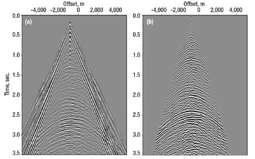
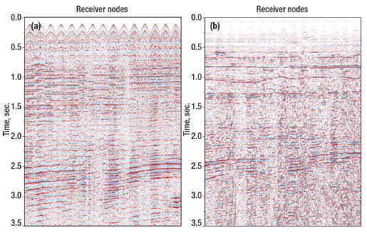
Figure 1 shows an application of the above described work flow to a 3D node data set. The common receiver gather has, after multiple attenuation, a higher signal-to-noise ratio. Figure 2 illustrates the effect on the final image in a near offset stack of a shotline with 16 receiver nodes by comparing the raw stack with the de-multipled stack. Applying the wave equation to multiple attenuation considerably improved the quality of the image.
 |
|
Fig. 1. 2D slice of a real 3D node data set. (a) Raw receiver gather after calibration. (b) After multiple attenuation.
|
|
 |
|
Fig. 2. 2D near offset stacks of a shot line with several receiver nodes corresponding to the example in Fig. 1. (a) Raw receiver gathers. (b) After multiple attenuation.
|
|
VELOCITY ESTIMATION
Stereotomography is a slope tomography method that has been shown to be very effective and practical, as it provides a smooth background velocity model which can, subsequently, be used as an input model for preserved-amplitude pre-stack depth migration.5 One of the particularities of stereotomography is that it estimates velocity parameters, as well as structural parameters (local pieces of reflectors). Although, traditionally, the model is described by smooth parameters such as B-splines, it is possible to introduce layer parameters.6 These allow inversion toward models which have a more geological meaning and help the stabilization of velocity estimations. In particular, we use these layers for anisotropic inversion.7 The presence of layers and reflectors allows the pairing of PP and PS key reflectors, as well as well tying.
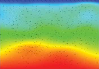
The difficulty of applying stereotomography to node data is that this method requires lateral coherency in both common-receiver and common-shot gathers. The lateral coherency on common-shot gathers is not sufficient with node acquisitions due to their sparse deployment. However, previous studies have shown that the challenge can be bypassed using the reciprocity property of the PP-Green’s functions.8 In case only the pressure wavefield is used from node data, the constraint on anisotropy has to be completed by well tying. Figure 3 shows an isotropic example of stereotomography applied to real node data.
 |
|
Fig. 3. Estimated stereotomographic model using real node data from the North Sea. The model consists of a smooth background velocity model and dipbars (estimated local reflector pieces). The smooth velocity model can be used for full waveform inversion or migration.
|
|
Background velocity models estimated from node data can be derived by the first arrival traveltime tomography method using refracted waves. However, this method faces some limitations when low-velocity zones are present, such as gas clouds. To our knowledge, reflection traveltime tomography cannot be adapted to node data without further assumptions to compensate for the lack of coherency in the common midpoint gathers and, therefore, stereotomography is the most appropriate method for such acquisitions.
FULL-WAVEFORM INVERSION
The background velocity model, estimated for example by stereotomography, can be improved by Full-Waveform Inversion (FWI). Nodes are well suited for FWI as they can provide long offset data. FWI provides, in addition, a quantitative estimate of physical earth parameters. This method aims at determining a best-fit model by iteratively minimizing the misfit between the observed waveform and the synthetic waveform data calculated from forward modeling. It has the potential to estimate wavefield attenuation, reflector depth and geometry, and background velocity by inverting amplitude, traveltime and move-out information contained in pre-stack seismic data.9
FWI allows reconstructing the full wavenumber range contained in the data and drastically improves the resolution of the derived tomographic models. Although the theory for the acoustic and elastic waveform inversions has existed since the 1990s for both time and frequency domains,10,11 application to real datasets have remained limited until the last few years due to high computational cost, strong sensitivity to the starting model and noisy datasets. Nevertheless, over the last five years, applications of full-waveform inversion methods to complex geological areas have shown that full-waveform inversion can improve the resolution of tomographic images, and that FWI in the frequency-domain is well suited for large offset seismic datasets such as those provided by node data.12-15
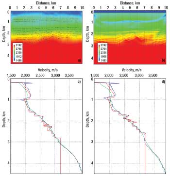
It is also well known that since FWI is a linearized non-linear inverse method, its results are strongly dependent on the initial velocity model. To avoid cycle skipping effects, the starting model needs to explain the dataset within half-wavelength. To derive this starting model, we use stereotomography. Figure 4 shows an example of the combination of stereotomography and full-waveform inversion applied on a synthetic model provided by StatoilHydro.16 The subsequent application of full waveform inversion clearly improves the resolution of the stereotomographic velocity image.
 |
|
Fig. 4. Combination of stereotomography and full-waveform inversion. a) Velocity model derived from stereotomography, b) velocity model obtained by full-waveform inversion after inversion of frequency component 13Hz. Comparison of velocity profiles extracted from the true model (red curve), steretomographic (green curve) and full-waveform model (blue curve) at c) 3.3 km and d) 5 km.
|
|
ANGLE MIGRATION
Migration should preferably be performed in the angle domain because it allows subsequent amplitude vs. angle analysis without the need for an approximate a posteriori offset-to-angle conversion. In case of strong lateral velocity variations, it has been shown that the angle domain can reduce kinematic artifacts due to triplications.17
It is well known as well that migrated images are polluted by migration noise, known as migration smiles, which is important when the distance between the receiver increases. This noise can be removed if, for example, the geological dip is known. Then, we can limit the migration operator so that only constructive interferences sum during the migration process. The geological dip can be estimated from the stereotomography output.18
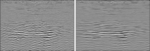
Stereotomography provides, in addition to the velocity model parameters, local pieces of reflectors. This structural information can be used during the migration to improve the image. Figure 5 shows migrated results of a real dataset from the North Sea recorded by nodes. On the left, a conventional constant 30° limitation of the migration aperture, with respect to the vertical axis, was used, whereas on the right we applied the limitation of the migration operator using knowledge of the geological dip. Even with 400 m between nodes, the migration smiles are reduced in the right picture. This noise removal makes the post-processing, such as amplitude vs. angle analysis and interpretation, more reliable. One observes that in both images the right hand side seems not to be properly imaged, Fig. 5. This is interpreted as too low an estimated velocity field due to a limited acquisition.
 |
|
Fig. 5. Migrated stack with a conventional 30° aperture (left), and with our adaptive limitation of the migration operator (right).
|
|
CONCLUSION
We have further developed existing tools which aim at retrieving as much information as possible from OBS data. These tools cover multiple attenuation, background velocity estimation, full waveform inversion and pre-stack angle migration. The novelty of the present work is the extension and application of these tools to node data in a comprehensive workflow. The results obtained so far are promising and show that for node data, good results are obtained when taking into account the particularities of this acquisition system.
The main limitation for our workflow is still the PS-wave imaging. A macro velocity model estimation method is under development that takes S-waves into account and anisotropy, constrained by matching PP and PS key reflectors, without necessarily using well data. 
ACKNOWLEDGMENT
The authors thank the Norwegian Research Council (grants 159117/I30 and 162612/S30) for sponsoring this work, SeaBed Geophysical AS for providing the real dataset and StatoilHydro for partially sponsoring the work and providing the synthetic model.
LITERATURE CITED
1 Fagin, S., “Model-based depth imaging,” Society of Exploration Geophysicists, 1998.
2 Amundsen, L., Ikelle, L. T. and L. E. Berg, “Multidimensional signature deconvolution and free-surface multiple elimination of marine multicomponent ocean-bottom seismic data,” Geophysics, 66, 2001, pp. 1594-1604.
3 Amundsen, L., Arntsen, B., Aronsen, H., Osen, A., Richardsen, G. and M. Thompson, “Fast deterministic designature/demultiple of 2D and 3D 4C-OBS data,” OTC 16943 presented at Offshore Technology Conference, Houston, Texas, 2004.
4 Traub, B., Ngyen, A. K. and M. Riede, “Pre-processing workflow for 3D OBS data for multiple attenuation,” presented at EAGE, Expanded Abstracts, London, June 11-14, 2007.
5 Billette, F. and G. Lambaré, “Velocity macro-model estimation from reflection seismic data by stereotomography,” Geophysical Journal International, 135, 1998, pp. 671-690.
6 Foss, S. K., Ursin, B. and M. de Hoop, “Depth-consistent reflection tomography using PP and PS seismic data,” Geophysics, 70, 2005, pp. U51-U65.
7 Nag, S., Alerini, M., Duveneck, E. and B. Ursin, “2D stereotomography for anisotropic media,” SEG, Expanded Abstracts, New Orleans, Louisiana, Oct. 1-6, 2006.
8 Alerini, M., “Stereotomograpy for nodes data,” presented at EAGE, Vienna, June 12-15, 2006, pp. B043.
9 Hicks G. J. and R. G. Pratt, “Reflection waveform inversion using local gradient methods: Estimating attenuation and velocity over a gas sand deposit,” Geophysics, 66, 2, 2001, pp. 598-612.
10 Tarantola A, “A strategy for non linear elastic inversion of seismic reflection data,” Geophysics, 51, 1986, pp. 1893-1903.
11 Pratt, R.G, “Inverse theory applied to multi-source cross-hole tomography. Part II: Elastic wave-equation method,” Geophysical Prospecting, 38, 1990, pp. 311-330.
12 Ravaut, C., Operto, S., Improta, L., Virieux, J., Herrero, A. and P. Dell’Aversana, “Multiscale imaging of complex structures from multifold wide-aperture seismic data by frequency-domain full-waveform tomography: application to a thrust belt,” Geophysical Journal International, 159, 2004, pp. 1032-1056.
13 Dessa J.X. , Operto S., Kodaira S., Nakanishi A., Pascal G., Virieux, J., Uhira K. and Y. Kaneda, “Multi-scale seismic imaging of the Eastern Nankai trough by full waveform inversion,” Geophysical Research Letters, 31, L18606, 2004.
14 Operto S., Ravaut C., Improta L., Virieux J., Herrero A. and P. Dell’Aversana, “Quantitative imaging of complex structures from multi-fold wide-aperture seismic data: a case of study,” Geophysical prospecting, 52, 6, 2004, pp. 625-651.
15 Brenders D. and R. G. Pratt, “Efficient waveform tomography for lithospheric imaging: Implication for realistic, 2-D Acquisition geometries and low-frequency data,” Geophysical Journal International, 168, 2006, pp. 152-170.
16 Stovas, A., Landrø, M., and B. Arntsen, “A sensitivity study based on 2D synthetic data from the Gullfaks Field, using PP and PS time-lapse stacks for fluid-pressure discrimination,” J. Geophys. Eng., 3(4), 2006, pp. 314-328.
17 Xu, S., Chauris, H., Lambaré, G. and M. Noble, “Common angle image gather : a strategy for imaging complex media,” Geophysics, 66(6), 2001, pp. 1877-1894.
18 Alerini, M, Riede, M. and B. Ursin, “Limited-aperture migration by sterotomography output,” EAGE, Expanded Abstracts, London, June 11-14, 2007.
|
THE AUTHORS
|
|
|
Mathias Alerini is a research scientist at the Seismic and Reservoir Technology department of SINTEF Petroleum Research in Trondheim. He received a DEA and a DESS (M.Sc. equiv) from Paris VI, France, and a PhD from The Ecole des Mines de Paris, France, in 2002.Within SINTEF, he did a postdoc in collaboration with the University of Trondheim (NTNU). His main fields of competence are ray-based depth imaging on multi-component/OBS data.
|
|
| |
Barbel Traub is a research scientist at the Seismic and Reservoir Technology department of SINTEF. She holds a Diplom (M.Sc. equiv.) from Universität Karlsruhe (TH), Germany, and received a PhD from Edinburgh University, UK in 2005. She has been active in seismic anisotropy parameter estimation and seismic processing, analysis and modelling.
|
|
| |
Céline Ravaut is a research scientist at SINTEF. She holds a DEA (M.Sc. equiv.) from Paris VII, France, and a PhD from Paris VI in 2003. She worked at the Dublin Institute for Advanced studies, and studies advanced processing of OBS data, full-waveform inversion and seismic tomography.
|
|
| |
Steinar Nag has been a research scientist at SINTEF since 2005, while working on his PhD in collaboration with NTNU, where he also received a Masters degree in mathematics. Recently, he has been working on ray tracing and seismic velocity estimation in anisotropic media.
|
|
| |
Menno Dillen is a senior scientist at SINTEF. He received a MSc and a PhD from Delft University of Technology, the Netherlands. He did a postdoc in Delft and was a research associate at the University of Texas at Dallas. Before starting at SINTEF at the end of 2005, he was a senior research scientist at dGB Earth Sciences, Enschede, the Netherlands.
|
|
| |
Séverine Pannetier Lescoffit obtained a Diplome d’ingenieur (equivalent to MSc) from Ecole Nationale Superieure de Géologie, Nancy, France, in 1998. She has been with SINTEF Petroleum Research for the past 5 years as a geophysicist and, recently, as assistant research director for the seismic and reservoir technology department.
|
|
|


