SPECIAL FOCUS: OFFSHORE REPORT-EXPLORATION
New seismic seafloor acquisition
offerings proliferate
Explorationists and reservoir engineers now have more choices for more applications, although 4D is the most likely use.
Perry A. Fischer, Editor
The benefits of acquiring data on the seafloor seem obvious. So do the challenges. If the installation is permanent, numerous surveys for 4D monitoring can be acquired very cheaply. If it’s a temporary node acquisition, the nodal positions can be located and repeated very accurately. Also, if multi-component data is required, the seafloor is the only way to get it. But as depth increases, so do costs and the ability to get everything to work at high pressures.
For permanent installations, the trend is for purely fiber optic systems, in part to mitigate potential longevity problems with water/electricity. Four companies showcased their seafloor systems at EAGE, recently held in London, and are presented here.
PGS
Fiber optic sensor systems have been under development for 10 years at the company. Several generations of prototypes have been produced. Ongoing projects include applications for streamers and near-field airgun recording. The focus for the system is primarily for reservoir monitoring in permanent installations similar to Valhall field.
The telemetry architecture is Dense Wavelength Division Multiplexing (DWDM), a technology that is widely used by the telecommunications industry. It provides flexibility in terms of dynamic range and the ability to record several thousand channels via a small bundle of optical fibers.
The system is powered only by light, without any electronics at the “wet end” of the streamer. A prototype used 10 wavelengths with a capacity of 240, 4C channels (960 channels total). Multiplexed and modulated light is sent into fibers in the optical cable. It is then distributed to the optical sensors.
Phase-modulated laser light is passed through Michelsen micro-interferometers, which convert strain resulting from changes in acoustic pressure into a phase change of the carrier light signal. This phase shift is extracted from the light returning from the sensors, which is de-multiplexed and de-modulated. This allows for the independent measurement of the phase shift from each sensor, which is output as a seismic trace.
PGS has developed optical sensors for both P- and S-wave measurement, including an optical hydrophone that has been qualified to operate in 3,000-m depths. The unit was tested to have a scale factor of -140 dB re rad/µPa ± 1 dB over all operational pressures and temperatures. This translates to a noise floor below 1 µB. A 3-axis optical accelerometer has also been developed. It is also 3,000-m rated when suitably mounted in a urethane-filled pressure housing.
A fiber optic 4C seafloor system was successfully demonstrated in the North Sea during late 2003. PGS says that the resulting data was very similar to the company’s electrical OBC system, and showed the performance required for deepwater applications. In the summer of 2006, a test was performed in the Gulf of Mexico, in 30-m water depths, with permanent system deployment in mind. A number of stations were deployed, both trenched and untrenched. The main purpose of test was to verify performance of a new optical accelerometer. It was deployed parallel to the company’s conventional electric-powered 4C cable, Figs. 1 and 2.
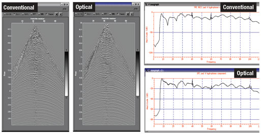 |
Fig. 1. Comparison of conventional electrical hydrophone and optical hydrophone in Gulf of Mexico test.
|
|
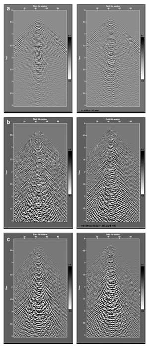 |
Fig. 2. Comparison between conventional (left side) and fiber optic (right side). Note: in all cases, data has been rotated, and comparison is between non-trenched cables: (a) Vertical component; (b) X-line; (c) In-line.
|
|
In October 2006, the company moved to a dedicated facility in preparation for permanent cable fabrication. First deepwater installation of the new permanent fiber optic system is planned for a major operator this year.
SERCEL
This company is offering a new seafloor cable system, as well as an autonomous node system.
Ocean bottom seismic. Sercel’s new SeaRay is a redeployable 4C OBC seismic acquisition system built on the company’s series Digital Sensor Unit (DSU). The new system uses 428XL DSU sensors. It is also compatible with its 408UL system. The new OBC can operate in 300 m water depth (500 m [1,640 ft] with special handling care). There is a smaller, lighter cable option for operations in less than 100 m water depth. The system architecture is scalable up to 100,000 channels at a 2-ms sampling interval.
The sensor pack is somewhat flat, to aid in keeping it coupled against the seafloor, although the sensors are insensitive to any tilt, thanks to the company’s omni-tilt MEMS sensor technology. Holes within the aluminium-bronze body aid in hydrophone coupling, Fig. 3. There is a built-in multi-route system for data telemetry redundancy (Fig. 4), and a similar power redundancy system, in the event of a shorted/cut wire. Seismic contractor Geokinetics has tested a short array in the Red Sea, and has ordered another system for testing in the near future.
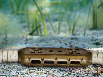 |
Fig. 3. Sercel’s new OBC is relatively flat to aid in seafloor coupling; holes aid in hydrophone coupling.
|
|
 |
Fig. 4. The new OBC is fault tolerant for telemetry as well as power.
|
|
New OBS node. Conventional streamer surveys are operated with a single seismic vessel and have narrow azimuthal coverage. Whatever is not illuminated cannot be imaged. Wide azimuth coverage is important for imaging under complex overburden structures such as salt.
Two techniques that achieve wide azimuth geometry offshore are multi-vessel streamers and OBS nodes. OBS nodes are much more practical in the presence of obstacles such as production facilities, and for 4D seismic monitoring, OBS has better positioning repeatability than streamers. In addition, OBS provides multi-component data, which might be highly desirable where shear-waves are needed, such as over gas-occluded reservoirs.
Several years ago, Veritas (now part of CGGVeritas) began evaluating existing scientific autonomous nodes for routine oilfield use. After several tests and years of consideration, the company chose to build its own node.
One critical technical goal was to reduce the power consumption of the data recorder and clock. This would allow increasing seafloor operating time, reducing the size and weight, and allow node redeployment without charging or changing batteries. The necessary technology was deemed available. The European firm SEND was contracted to develop the new recorder.
The technology has developed rapidly, with a field test of two prototype units conducted in the UK during August 2005. Three months later, three prototype units were tested in a pond in Kansas. The company then manufactured more units and completed an alpha test with 20 nodes piggy-backed on a transition zone project in Louisiana in mid-2006. Thirty more units are being built, and a number of test projects are being discussed with clients.
The node, called Trilobit, can operate in 4,000-m depths and is ROV deployed. It uses a Galperin 3C omni-tilt geophone package (no gimbals) to measure the seabed P- and S-waves and a hydrophone to measure the P-wave in the water. The design comprises circular symmetry and low center of mass, while a special base-plate design helps liquid to be pushed outward when the unit settles on the seafloor. The custom-built, low power recording unit and clock allows recording for 90 days at 2-ms sampling.
The unit is intended for ROV deployment in deep water, and the smooth, flat cover surface is for ROV suction-cup handling. The cover is not pressure sealed, so water floods the inside of the unit, which helps keep the weight down. Alkaline batteries power the unit.
Test data were acquired on a 20-unit deployment in a conventional transition zone project, Fig. 5. The survey was in shallow water over a salt dome, in southern Louisiana. TZ survey dynamite shots of 5 kg at 100 m depth were recorded. Data from one of the units is shown in Fig. 6. Clearly seen are primary compression and shear waves.
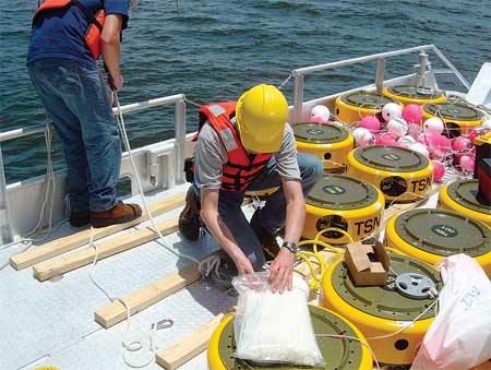 |
Fig. 5. One of several tests on CGG Veritas’ new node system.
|
|
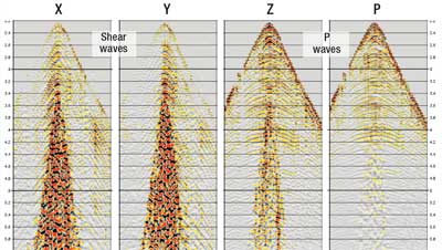 |
Fig. 6. Data from above a salt dome in Louisiana. The data from the three geophones, in Galperin arrangement, have been rotated to two horizontal components, X and Y, and a vertical component Z. The hydrophone data is labeled P. There is no shear-induced noise evident on the vertical component. The strong shear event on the horizontals (and weaker on the vertical) is a Stonely or Love wave in the mudline.
|
|
WAVEFIELD INSEIS
In a development history that dates back to 1985, Optoplan AS has been in the forefront of developing fiber optic technology for oilfield use. The approach has been Fiber Bragg Grating (FBG) technology. Weatherford acquired the technology in 2002. In 2005, the company began to test a fiber optic ocean bottom seismic array. Wavefield Inseis acquired 35% of Optoplan from Weatherford in 2007, with an option to acquire more, and formed Optowave AS to commercialize fiber optic ocean bottom cable for permanent 4C/4D use.
The OBS application of the optical sensing technology has been developed through a collaboration between Statoil and Optoplan AS. The system has been qualified in different settings ranging from 40 m to 300 m water depth. The seismic sensors are fully fiber optic-based; i.e., each 4C OBS station consists of a 3C fiber optic accelerometer unit and a fiber optic hydrophone.
During the first of two experiments, two fiber optic cable units were deployed in 2005 in the 40-m deep harbor in Trondheim, Norway and, for comparison, a MEMS-based system was deployed in parallel. All three cables were buried at about a 1-m depth in the seafloor.
In 2006, a single fiber optic OBS cable was deployed in 300 m deep water adjacent to the Statoil methanol refinery at Tjeldbergodden, Norway. The seismic data generated in Trondheim has been analyzed and compared to data from a test cable based on MEMS technology, which was deployed at the same location. Analysis of the data from both Trondheim and Tjeldbergodden confirms the system’s high degree of vector fidelity, high signal-to-noise ratio and good ground-station coupling. These tests confirm that fiber-optic sensor technology, for applications within permanently buried seismic acquisition systems, is viable for life-of-field seismic projects, Fig. 7.
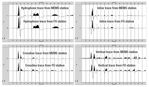 |
Fig. 7. Wavelet comparison of Fiber Optic (FO) and MEMS-based sensors. Fiber optic data resampled to 1 ms (MEMS data acquired at 1 ms).
|
|
Optoplan has signed a contract with Statoil for a permanent 4C reservoir monitoring pilot installation at its Snorre field in the North Sea during third quarter 2007.
STINGRAY
A unique optical architecture for high channel-count systems uses Time and Dense Wavelength Division Multiplexing. This method was developed and used for military applications through the consultancy QinetiQ. That technology, now called Fosar, is now being commercialized for oilfield use by a new company, Stingray Geophysical, in cooperation with a JIP, whose partners are BP, Chevron, Conoco-Phillips and Norsk Hydro. A poster at the recent EAGE (P191 Strudley and Nash) describes the architecture.
The 4C optical sensor unit consists of a hydrophone and three orthogonally mounted accelerometers. The sensors are based on a “reflectometric” interferometer. An acoustic pulse causes a strain in a coil of fiber, which imposes a phase change on an optical signal passing through the fiber by a combination of physical change in the length of the fiber and changes in the refractive index (the stress-optic effect). This phase change is measured in the “optoelectronic” system and may be related back to the input stress.
Optical power for the array is generated by the optoelectronic system, which may be located a considerable distance from the array-more than of 100 km is possible. The optoelectronic system consists of the lasers, control system and demodulation boards required to generate and process the light returning from the optical array.
Of the many possible multiplexing schemes, a combination of Time Domain Multiplexing (TDM) and Dense Wavelength Division Multiplexing (DWDM) offers some potential advantages. With this architecture, a single fiber-which can be a few meters to tens of meters long-wound on a coil, can act as a sensor. The sensor coils are spliced serially together, separated by a directional coupler with a reflective mirror attached to one port. The other port of the coupler is index matched to ensure suppression of multipath reflections.
As shown in Fig. 8, the sensor is interrogated with two optical pulses that are frequency shifted relative to each other and separated in time by twice the transit time in the sensor fiber. The return signal from the sensor consists of an overlap of the two pulses: one being the reflection from the first mirror forming the reference signal, and the other reflecting from the second mirror after passing through the sensor fiber. The overlapping pulses received at the photodiode generate the heterodyne carrier signal that contains the phase modulation associated with the seismic signal received at the sensor.
 |
Fig. 8. Architecture for Time Domain Multiplexing (TDM).
|
|
With the basic TDM architecture, the level of multiplexing that can be achieved is limited by a combination of sampling frequency and optical power budget. To achieve the multiplexing required for a high channel-count seismic array, an additional multiplexing step is needed. A combination of TDM and Dense Wavelength Division Multiplexing (DWDM) allows the level of multiplexing to be increased. As shown in Fig. 9, each TDM set of sensors forms one subset within a larger set of sensors; each TDM subset is interrogated by a different wavelength.
 |
Fig. 9. TDM architecture with DWDM added allows many more channels.
|
|
The multiple wavelengths needed to interrogate the full sensor set are separated out of the optical telemetry fiber using optical add/drop multiplexers. The returning reflections are coupled using the same add/drop multiplexers. At the array output, the different wavelengths are routed onto separate photodiodes using a wavelength demultiplexer. Using the combined TDM/DWDM architecture allows many hundreds of channels to be carried per fiber pair while maintaining acceptable system performance.
A field test was performed in November 2006 of a TDM/DWDM architecture optical sensor array. The test took place at the Bincleaves test site near Weymouth, UK. A number of seismic lines were acquired into both the optical array and a reference autonomous node using conventional electrical sensors. The data were comparable (Fig. 10), with a system noise floor below -140 dB g/rt Hz, maximum signal level of greater than 0.9 g in the seismic band and sensor to sensor cross talk better than -70 dB, confirming the viability of this approach for optical seismic sensing.
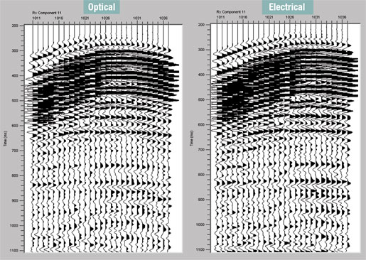 |
Fig. 10. Fiber optic data (left) and conventional electrical node data (right).
|
|
A new field test will soon be underway when a section of the fiber optic system is installed in Valhall field offshore Norway.
SUMMARY
The seafloor acquisition technologies presented here have been under development for many years. While contractors have always been quick to advocate new services, the high demand from oil companies for seismic services has spurred their development, especially where multi-component data is essential. While one of these is now commercial (Sercel’s SeaRay), the four fiber optic systems will see numerous pilots and tests that will quicken the pace to full commercialization. 
|

