Rapid progress in expandable liners and single diameter well construction
Rapid growth in expandable tubular usage continues. Long expanding casing runs are becoming routine. Single diameter wells will become a reality soon.
OIL COUNTRY TUBULAR GOODSRapid progress in expandable liners and single diameter well constructionExpandable tubular technology continues its rapid growth rate, as operators see its value. Although contingency is still its primary use, new field successes have bolstered the case that very long expandable casing runs are becoming routine, while true single-diameter wells will be a reality sooner than expected.Perry A. Fischer, Editor, and Lauren W. Raber, Associate Editor Whoever said that new technology takes over 20 years to be accepted in the oil patch must not have known about solid expandable tubular technology. Setting aside expandable screens, junction reforming and other non-casing-string applications, uptake of expandable casing has been relatively quick. There have been hundreds of installations comprising hundreds of miles of pipe. It has been used in wells more than 28,000-ft deep, and in wells with bottomhole temperatures above 400°F. Recent record lengths of expandable casing used as a liner and the first three-string run of true single-diameter wellbore prompt this update. KEY BENEFITS Although most often run as a contingency, solid expandable tubulars are increasingly incorporated into the wellbore construction as a planned design element.1 Perhaps “workaround” is a better word, since a pre-planned solution to an emergency is not really a contingency. Whatever the terminology, a growing number of operators are shifting their implementation of solid expandable tubulars from a problem-solving strategy to a cost/time-saving one. Time and cost. Most savings center on the reduction in borehole diameter, since every inch of wellbore larger than what is needed at the producing zone results in extra cost. This has been the driver behind Reduced Casing Clearance Programs and slimhole completions. From this ID reduction, the benefits multiply, ranging from less fluid used and fewer rock cuttings to dispose of (in zero-discharge drilling), to less rig time and the use of cheaper, smaller rigs. Cost savings could even shift the economic threshold for field development, or allow economic development of smaller reservoirs. A 2004 SPE paper put the savings at 59% for cuttings disposal, 38% for casing weight, cement volume reduction of 42%, and 44% less drilling fluid volume. With today’s spread rates, savings could easily amount to tens of millions of dollars.2 Also, by preserving hole size, especially in the case of an unplanned intermediate liner, casing diameter at the producing zone can result in better cash flow, and an otherwise undrillable well could become drillable. Borehole engineering problems. When an expandable liner is run because of a too-narrow pressure window in a section of the planned borehole, an expandable solution might be the only way to get the well drilled. The pressure problem can occur because a depleted zone must be drilled through, in which case the operator might plan to “workaround” the problem using expandables. It can also occur when an over-pressured zone must be drilled through. It should be mentioned that drilling with casing technology may help alleviate these problems as well, given the benefit of the “plastering effect” (vs. mudcake), as well as the more narrow annulus used in that method. Enventure Global Technology commented that it was “looking into” drilling with expandable casing. Casing has been successfully expanded against a borehole that was not cemented, both with external casing packers in the form of swellable elastomers, and without elastomers, where the casing “clads” the formation. Well construction issues interact. Problems that arise which decrease the ID of the completion might restrict production rates. Sometimes, this can be the over-riding need for using expandables. ERD. Expandable casing, especially as a single-diameter borehole, has been garnering greater consideration in Extended Reach Drilling (ERD).3 Success in ERD relies on adequate weight on bit and minimizing friction. Steel, of course, has less friction than formation. Drillstring design plays a key role, but by preserving a continuous and large, say, 10-in. casing, contact with the drillstring, and thus, friction, is minimized, while usable ID for optimum production is preserved. BP is reportedly considering expandable technology for a 40,000+ ft ERD project at its Liberty prospect off Alaska’s North Slope. A well-design feasibility study was conducted for a major North Sea operator. The study showed potential lateral reach increases of 25% to 100%, with reduced drilling problems in both fields. Other drilling performance and cost studies in the same two North Sea fields indicated that by applying solid expandable tubulars and/or single-diameter technology, well costs and times can be reduced by at least $40 million, or 30% to 50% of the current drilling cost and time. The model considered the effect of incorporating two solid expandable tubular liners into the well design, which showed a potential 50% increase in lateral reach. Up to about 7.5 mi (12.7 km) reach can be achieved by installing two successive solid expandable tubular liners.3 Further, the reach can be increased to 9.5 mi (15 km) when using 9 to 11 successive single-diameter liners. RECENT RECORD EXPANDABLE CASING RUNS All solid expandable tubulars conserve material mass during expansion. Thus, wall thickness must thin very slightly, while length shrinks about 4%. Also, gouges and deep scratches can act as “seeds” for rupture, so it is necessary to use handling and running techniques similar to Chrome 13 pipe. Expandable casing as a liner. When expandable casing is run as a liner or intermediate casing string, a single string of casing is run in hole (RIH) and a one-trip expansion occurs. When run as a result of an unplanned contingency (i.e., an unforeseen problem), the well will have a reduction in ID, just as conventional liners do. The benefit is that ID loss will not be as large as with conventional pipe, since the hanger is just elastomers sandwiched between a long overlap section. In the case of a planned contingency, where the operator has some reason to believe that a problem might occur at a specific depth, an oversized section (or bell) can be run on the end of the parent casing to that depth in order to avoid the ID reduction. Baker Hughes began using a new Recess Shoe (Fig. 1) that includes a profile for locating the expandable hanger and specialized cement ports, as discussed below. Some under-reaming is likely necessary in these cases for cement-sheath thickness. Should these planned “workarounds” not be needed, the operator need not use them for expanded pipe. Baker Hughes calls its expandable liner system linEXX and uses the word “monobore” in describing some applications.
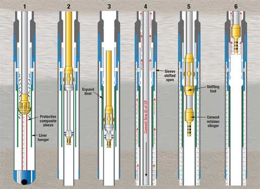
In a true single-diameter well, the bell must be formed, in situ, at the bottom of each string for the ID to remain unchanged, no matter how many strings of casing are run. Enventure’s name for its system to accomplish this is MonoDiameter (not to be confused with the term “monobore,” which is completely different system-a liner system-from BHI). The process is discussed in more detail in the next section. First, we describe a couple of recent record liner runs. Enventure, working with operator Nexen, set a world record in late March for installing the longest expandable liner system to date-6,867 ft of 7 5/8 x 9 7/8-in. pipe in openhole at Nexen’s Aspen-1 well in the Gulf of Mexico, drilling in 3,143 ft of water. The longest expandable liner before this was about 5,000 ft. The operator was drilling through depleted sands in its deepwater well. Through the use of expandable tubulars, Nexen isolated the depleted zones and attained the desired hole size. It was worth the cost and effort to maximize the hole size to improve production levels and lower mechanical risk in the completion. Nexen chose Enventure’s Openhole SET system to reach TD with a 7-in. flush-joint liner, as opposed to a conventional 5½-in. liner that would have limited production by 5,000 bopd. The record installation was in a second sidetrack at 20,000 ft. The operator’s first sidetrack failed due to stuck drillstring after encountering high-pressure sands. The operator drilled an 8½-in. hole, underreamed it to 9½-in., then ran and cemented the expandable liner. Expansion required 3,600 psi of pressure to start and provided a 7.710-in. ID with clearance for a subsequent 7-in. production liner. A collaboration between BP and Baker Oil Tools has proven the feasibility of a new expandable liner system, which it calls the monobore expandable liner extension system. The liner expansion of 1,514 ft was in a commercial BP well in southeast Oklahoma, which was air-drilled to a 4,100-ft depth. The installation procedure went as follows:
It took about 18 hours to expand the 1,514-ft extension, including RIH time, although typical expansion rates are in the 200-ft per hour range. The Recess Shoe has been run on at least five North Sea wells as a contingency, but the full system was not deemed necessary to run on those contingencies.
Expandable casing as single-diameter wellbore. In a true single-diameter well, multiple runs of pipe are expanded so that ID does not decrease, and a bell, or flared, shape is established in the upper pipe into which each lower, subsequent pipe is expanded. A metal-to-metal seal anchors the lower pipe into the bell section. For such single-diameter wells, two expansions, or one over-expansion, are needed. One expansion gets the pipe’s OD to match the ID of the parent, or upper pipe. A second expansion creates the same ID in both pipes, which requires that in the overlap section, the upper pipe will take on a bell shape. Ideally, both expansions should be done in a single trip. The overlap area, or bell, is the limiting factor for pipe size. Thus far, the practical limit of plastic deformation without risking pipe fracture is an expansion ratio of 30%. Expanding 9 5/8 x 11 3/4-in. pipe results in a 10.4-in. ID. This yields a basic expansion rate of 17%. The bell must expand 24%, which is within the feasible expansion ratio. This makes 9 5/8 x 11¾-in. pipe a practical MonoDiameter size.2 However, applying the expansion process to 5½ x 7-in. pipe yields a 6.1-in. ID, and a 25% expansion, while the corresponding bell must expand 42%. This exceeds the practical expansion limit. The smallest practical diameter that can be expanded into a bell for monodiameter applications is 7-5/8 x 9-5/8-in. pipe, which yields an 8-in. ID with a 19% expansion, while the bell expands 29%.2 Previously, two experiments were conducted to see if the bell and its overexpansion could be achieved. In 2002, two short strings of casing were expanded in a Shell South Texas well. This required multiple trips and one expansion up and one expansion downward to form the necessary bell in the bottom of the first string. In late 2004, an experiment was completed with an “all-in-one” tool that was designed to perform the necessary expansions in one trip (see World Oil, July 2005). Two strings were run, and a bell was formed in the bottom of the second string, all from the bottom up. Enventure recently completed a new world record-a true single-diameter wellbore over three separate strings. The job was completed in a newly drilled well under the operating supervision of Enventure. In addition to the normal expansion, two bells were formed in the bottom of the first and second strings, which received the expandable strings on the second and third runs. The 1st, 2nd and 3rd runs were done in the vertical, build, and highly deviated well sections, respectively, Fig. 3. A separate trip cut off excess pipe above the bell.
BOTTOM-UP vs. TOP-DOWN A debate exists (especially among the service providers, as one might expect) regarding the pros and cons of bottom-up expansion vs. top-down expansion. What they have in common is that the cemented, expanded casing is not centralized, although Baker says it will shortly introduce an expandable casing centralizer. If the free end of the liner, or any unexpanded part, should become stuck, the liner would become increasingly in tension and would try to part as it shortens. Presumably this would be rare, since getting the liner to bottom would be the most likely time it would get stuck, not as it shortens. But it’s possible. The two systems have comparable metallurgy, so the rate at which the cone can be driven should be comparable. But there are differences in the two systems; here are some of them: Bottom-up expansion employs hydraulic pressure and/or mechanical force (it can be both, but is primarily hydraulic) to drive the cone up through the expanding tubular via pin-up connections, with a typical expansion rate of 400-500 ft/hour, including breaking out drillstring connections, racking the drillstring to the stand, re-establishing pressure and continuing expansion. The bottom-up process:
Top-down expansion relies on pressure in the workstring to push the cone down via a stroke-out pipe. Typical expansion rates are 200 ft/hour, including the stroke/re-set/stroke time. Characteristcs of this method include:4
So, there are differences between bottom-up and top-down, but the success rates are very high with both methods. Until there is a much larger number of failures, it may be impossible to determine which method has an edge in success rates and mitigating the effects of problems. Presumably, the marketplace will determine this in time. It may well be the case that the best method remains arguable for a given application. CONCLUSION There are increasing numbers of applications for expandable liners and, eventually, single-diameter wells. The term “contingency” is misused with growing frequency, as operators learn that pre-planning the use of expandable casing across known or just suspected trouble zones can make an otherwise undrillable well drillable. It can also increase production to the extent that it preserves completion ID. The new systems that allow monobore liner extensions and single-diameter wells use complex downhole assemblies-these are working. Installation times and experience using these tools will only improve, as operators realize that they have new options in the world of expandables. Click here for a complete list of World Oil’s annual expandable technology reports.
|
- Coiled tubing drilling’s role in the energy transition (March 2024)
- Using data to create new completion efficiencies (February 2024)
- Digital tool kit enhances real-time decision-making to improve drilling efficiency and performance (February 2024)
- E&P outside the U.S. maintains a disciplined pace (February 2024)
- Prices and governmental policies combine to stymie Canadian upstream growth (February 2024)
- U.S. operators reduce activity as crude prices plunge (February 2024)
- Applying ultra-deep LWD resistivity technology successfully in a SAGD operation (May 2019)
- Adoption of wireless intelligent completions advances (May 2019)
- Majors double down as takeaway crunch eases (April 2019)
- What’s new in well logging and formation evaluation (April 2019)
- Qualification of a 20,000-psi subsea BOP: A collaborative approach (February 2019)
- ConocoPhillips’ Greg Leveille sees rapid trajectory of technical advancement continuing (February 2019)

