GEOLOGY AND GEOPHYSICS
Why seismic sequence stratigraphy?
Detailed seis-strat interpretation can help engineers solve perplexing drilling and field development problems.
Dr. Walter W. Wornardt, Micro-Strat Inc.
Both exploration and exploitation programs can be greatly enhanced by applying seismic sequence stratigraphic analysis. It has dramatically increased the explorationist’s ability to interpret rock types associated with AVO anomalies and to predict hydrocarbons where AVO anomalies do not exist. This technique gives the explorationist the ability to recognize, discover and evaluate new hydrocarbon reservoirs and to reduce the risk in management’s decision making. The play concepts, source, seal and traps associated with different reservoir sands and their associated lowstand, transgressive and highstand systems tracts are an important aspect of this analysis.
From an engineering perspective, seismic sequence stratigraphy can explain:
- Why one well has two pay sands, while another well in the same field has only one pay sand
- Why a waterflood does not work
- How to be more efficient in delineating and developing a new field.
Seismic sequence stratigraphy analysis is the integration of high-resolution biostratigraphic and paleobathymetric data, well-log signatures and seismic-reflection profiles,1 Fig. 1.
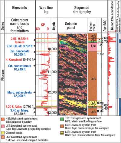 |
Fig 1. The sequence stratigraphic depositional model shows sequence boundaries, maximum flooding surfaces and systems tracts in a well.
|
|
This methodology permits the geologist and geophysicist to divide a stratigraphic section in a well and on a seismic section into a series of rock packages called third-order depositional sequences, chronostratigraphic maximum flooding surfaces, sequence boundaries and systems tracts.2 These sequences are subdivided into lowstand, transgressive and highstand systems tracts on the basis of characteristic lithology, fossil abundance patterns, paleobathymetry, well-log signatures and seismic reflection patterns, Fig. 1.
These surfaces are age dated with high-resolution biostratigraphy and are correlated with a cycle chart, Fig. 2. This methodology has increased the ability of explorationists to interpret rock types associated with AVO anomalies and predict, ahead of the drillbit, the type of reservoir sand they may encounter in areas where AVO anomalies do not exist.
 |
Fig. 2. This Miocene sequence chronostratigraphy for the Gulf of Mexico links fossil occurrences to geologic time.
|
|
The most important recent contribution to seismic sequence stratigraphy has been the addition and integration of high-resolution biostratigraphy.3 These detailed data sets from high-resolution checklists are important because they provide diversity and abundance of species, marker species, and relative and numerical ages.
In turn, histograms of species’ diversity and abundance provide an accurate means of identifying and age dating the maximum flooding surfaces (timelines), maximum flooding surface condensed sections and slope fan condensed sections.4 The histogram patterns also provide a means to recognize systems tracts and their boundaries. The maximum flooding surface can be age dated and identified on well logs and seismic, Fig. 3. They are important because they are associated with source rocks and provide a seal for hydrocarbons.
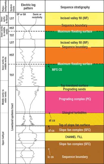 |
Fig. 3. Sequence and systems tract reservoir sands correlate with paleopathymetry, well logs and lithofacies.
|
|
Sample-by-sample paleobathymetry provides a means of accurately identifying the paleo water depth in which the reservoir sands were deposited. In turn, it provides a means to differentiate the various systems tracts associated with shallow or deepwater reservoir sands, Fig. 3. For instance, the blocky well-log signature of the deepwater lowstand systems tract basin floor fan complex is associated with ecozones 5–6; slope fan channel sands are associated with ecozones 4–5.5; shingled turbidites are associated with ecozones 3–4, and shallow water incised valley fill is associated with ecozone 1. The various expressions of the systems tracts and their reservoir sands can be discussed in terms of seismic sequence stratigraphy, Figs. 3 and 4.
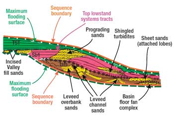 |
Fig. 4. Reservoir sands are distributed in a lowstand systems tract.
|
|
LOWSTAND SYSTEMS TRACT RESERVOIRS
The lowstand systems tract basin floor fan complexes are best developed in inter-slope basins in the middle to lower bathyal (1,500–6,000 ft). The exploration play concept is a deepwater, “pancake-shaped” reservoir with a box-car shaped log signature, with fairly clean continuous sandstones that thin in all directions from the center of the basin floor fan. From a development aspect, it is important to know if this sand is a channel sand or a basin floor sand. Pre-drilling estimates suggest that the channel interpretation will need 12 wells at $30 million each to develop the field or five wells at $30 million each to develop the basin floor fan interpretation. On seismic, the basin floor fan complex shows bi-directional downlap onto a sequence boundary.
The basin floor fan complex is developed in the Gulf of Mexico, Compos Basin of Brazil, North Sea, offshore southern California, San Joaquin Valley of California, offshore western South Africa, Western Australia, the Permian Basin of Texas and deepwater basins around the world.
The hydrocarbon source may be the overlying lateral hemipelagic shales and mudstones or leakage from deeper beds. Leakage upward into the slope fan facies is common because of a lack of seal. Therefore, stratigraphic traps are most likely where there is a significant basin floor fan condensed section at the base of a slope fan complex, Fig. 4. The traps are stratigraphic, but may be present on post-depositional structures.
The lowstand systems tract slope fan complex is best developed in the upper to lower bathyal (600–6,000 ft), Figs. 3 and 4. It commonly consists of stacked levee-channel deposits, characterized by a basal apron, attached lobes (sheet sands), sand-filled channel or overbank deposits and abandonment shales at the top. The slope fan complex typically pinches out by onlap in an updip direction near the outer-neritic to upper-bathyal interface.
While drilling, it is important to predict when these sands will be ahead of the drill bit. These sands are found after drilling through a maximum flooding surface in upper to middle bathyal water depths and into a “wormy” seismic pattern. The play concept involves bathyal water depth, discontinuous channel sands, widespread thin sands in overbank deposits, widespread sheet sands and layered or amalgamated sheet sands in a confined basin complex. On seismic, these slope fan complexes have a “wormy” pattern resting upon a basin floor fan complex or sequence boundary and below the parallel reflectors of the lowstand systems tract prograding complex.
These reservoir types are found in the deep waters of the Gulf of Mexico, West Africa, East China Sea, Indonesia, Compos Basin of Brazil, Andrews and Forties Fans in the North Sea, offshore southern California, San Joaquin Valley of California, offshore western South Africa, Western Australia, the Permian Basin of Texas and other deepwater basins around the world.
The source of the hydrocarbons is the levee-channel facies, the channel overbank condensed section on top of each of these levee-channel overbank deposits or the hemipelagic shales in the maximum flooding surface condensed section in the overlying transgressive systems tracts. The upper slope fan condensed section at the base of the lowstand prograding complex may form a major seal for the sands in the lowstand slope fan facies. Testing the sealing capacity may be important before producing from sands below the seal. Channel overbank condensed sections on top of the channel overbank deposits may also form a good seal. Overbank sand reservoirs are usually limited by levees and apron-edge pinch outs. The traps are usually stratigraphic and in a structural three-way closure.
The lowstand systems tract prograding complex may be thin, hemipelagic shale in bathyal environments, very thick, upward-shallowing, prograding deltas and shoreline sands in outer- to inner-environments, Figs. 3 and 4. The play concept involves variable, stacked, pro-deltaic, shoreface or fluvial sand reservoirs.
Correlation of producing sands must be made by matching the fossil shales between the sands, not by correlating the sands themselves. On seismic, this systems tract is characterized by parallel reflectors and transgressive surface erosion. These reservoir types are seen in the Tertiary of the Gulf of Mexico, West Africa, North Sea, Brazil and many other basins around the world.
The source may be the overlying hemipelagic shales in the condensed section in the transgressive systems tract, but the lateral seal may be poor. The traps are usually structural or may be due to compaction closure. Stratigraphic traps are present where the shallow water to non-marine facies is shale.
In the middle- and inner-neritic environments, the lowstand prograding complex is made of thick, interbedded, shoreface sands and neritic shales. The updip equivalent is commonly a fluvial incised valley fill. Sequence stratigraphy shows that correlating these sands, because they look alike, will probably be incorrect, Fig. 5.
 |
Fig. 5. The two sandstones in Wells A-1 and A-2 were deposited after and do not correlate to the lower shoreface sands in Well A-3.
|
|
The reservoirs are braided-stream sands with fair to good continuity. The source may be the overlying hemipelagic shales from transgressive systems tract above or deeper beds below. The overlying hemipelagic shales from the transgressive systems tract form a good seal, but the lateral seal is poor. The traps typically require structural closure.
TRANSGRESSIVE SYSTEMS TRACT RESERVOIRS
The transgressive systems tract consists of very thin hemipelagic shales in the bathyal environments. Basal shoreface sands with overlying shales in the outer- to middle-neritic environments become interbedded shoreface sands and neritic shales in the middle- to inner-neritic environments, Figs. 3 and 4.
Reservoirs are beach-shoreface sands with excellent porosity and permeability, with predictable linear trends. The lateral and overlying hemipelagic shales in the maximum flooding surface-condensed section form a potential source and very good seal. Traps are structural, but stratigraphic traps may be present.
The estuarine sediments deposited in the incised valleys during the transgressive systems tract are inferior to the fluvial reservoir sands deposited in the incised valleys during the lowstand prograding complex. Therefore, it is important to know if the reservoir sands were deposited in a lowstand or transgressive systems tract before developing the area as a field. The source may be the overlying hemipelagic shales from transgressive systems tract above or deeper beds below. The overlying hemipelagic shales in the transgressive systems tract form a good seal. The traps usually require structural closure.
HIGHSTAND SYSTEMS TRACT RESERVOIRS
The highstand systems tract is characterized by very thin, hemipelagic sediments in bathyal environments, which become a series of prograding sand and shale packages of the outer-neritic environment. They have a series of shoreface sands interbedded with marine shales in the middle- to inner-neritic environments.
Application of sequence stratigraphy to exploitation is seen in Figs. 5 and 6. The thick, oil-bearing sandstone in Wells A-1 and A-2 were correlated with three sandstones in Well A-3. Sequence stratigraphy shows that the two thick sandstones in A-1 and A-2 are part of a fluvial to estuarine incised valley fill that rests on a sequence boundary. These were deposited afterward and do not correlate to the lower shoreface sands in A-3, based on correlation of the fourth-order flooding surfaces timelines from well to well. Note that in Fig. 6 the hatchered area on the map may have potential for bypassed oil.
 |
Fig. 6. The map view of Fig. 5 shows the boundary between the two different sandstone facies.
|
|
The correct correlation of A-1 to A-3 also explains the production anomaly of water updip of oil. This map can be used to evaluate and plan injector/producer placement in the field. The highstand systems tract is characterized by thick prograding packages of sediments due to the decrease in the space available for deposited sediments, Fig. 5. The reservoirs are predominately discontinuous fluvial, deltaic facies with minor shoreface facies. Source is typically deeper beds.
Problems are common, including gas-prone organic shales in the highstand systems tract. Hemipelagic shales in condensed sections at the base of the highstand systems tract usually combined with similar shales in the upper part of the transgressive systems tract to form good seals in the maximum flooding surface condensed section. These condensed sections may be “stacked” into three or four condensed sections and mistaken for a “bright spot.” Leakage is common, laterally and updip, into the transgressive systems tract. Traps are predominantly structural associated with early migration.
SUMMARY
The sequence stratigraphic model provides the explorationist with a means to anticipate the overall thickness, lithofacies and potential reservoir rocks of the various systems tracts on well logs and seismic profiles. The rocks with the greatest hydrocarbon reservoir potential occur within the basin floor fan complex, the channel fill, channel overbank deposits, layered and amalgamated sheet sands in the slope fan complex, coastal belt sands and the incised valley fill sands.
Therefore the application of seismic sequence stratigraphy to hydrocarbon exploration and production provides the exploration and exploitation professional with the ability to:
(1) Predict ahead of the drill bit the sequential systems tracts, sedimentary strata type, stratal geometry and the reservoir rock types present in different systems tracts. This permits delineation of the stratal geometry of different systems tracts on the shelf, slope or basin, such as:
- Incised valley fill reservoir sands, perpendicular to strike, in shallow water in highstand and transgressive systems tract
- Prograding reservoir sands, parallel to strike, in a lowstand prograding complex
- Channel sands, perpendicular to strike in a lowstand slope fan complex
- Sheet sands, parallel to strike in a lowstand slope fan complex
- Basin floor fan: a pancake-shaped reservoir sand, lowstand basin floor complex; if the maximum flooding surface is not present, the boxcar-shaped sand may be a channel sand.
(2) Use the maximum flooding surface as:
- Timelines
- Correlation above and below the salt
- Adjust velocity below salt
- Hang cross-sections and flatten on important timelines
- Map sequences and systems tracts with reservoir sands
- Reduce the risk in management’s decision making.
The creative application of sequence stratigraphy provides an opportunity for companies to discover new oil and gas fields and extending existing ones. 
LITERATURE CITED
1 Sangree, J. B., P. R. Vail and R. M. Mitchum, Jr., “A summary of exploration applications of sequence stratigraphy,” GCSSEPM Foundation Eleventh Annual Research Conference Program and Abstracts, pp. 321-327, December 1990.
2 Vail, P. R. and W. W. Wornardt, “Well log seismic sequence stratigraphy: An integrated tool for the 90s,” GCSSEPM Foundation Eleventh Annual Research Conference Program and Abstracts, pp. 379-390, December 1990.
3 Shaffer, B. L., “The potential of calcareous nannofossils for recognizing Plio-Pleistocene climatic cycles and sequence boundaries on the shelf,” Gulf Coast Societies of Sedimentary Paleontologists and Mineralogists Foundation, Eighth Annual Research conference, p. 142-145, 1987.
4 Wornardt, Walter W., Jr., “Abundance and diversity histograms: The key to interpreting systems tracts, condensed sections and sequence boundaries,” Sequence Stratigraphy of European Basins, Dijon, France, pp. 102-103, May 1992.
5 Vail, P. R and W. W. Wornardt, Jr., “An integrated approach to exploration and development in the 90s” and “Well-log-seismic sequence stratigraphy analysis,” Gulf Coast Association of Geological Societies Transactions, vol. 41, p. 630, 1991.
6 Wornardt, Z. and V., “Three component sequence stratigraphy,” Gulf Coast Association of Geological Societies Transactions. vol. 42, pp. 501-516, 1992.
|
THE AUTHOR
|
|
Dr. Walter W. Wornardt is president of Micro-Strat Inc., Houston. He was a research scientist for Exxon Production Research Co. and Union Oil Research from 1965–1977. Wornardt was a professor of geology at University of Redlands and Humboldt State University from 1977–1981 and an adjunct professor at Rice University.
|
|
|

