|
Vol. 227 No. 9 |
| |
 |
Hurricanes of 2005 highlight need for improved mooring systems
New studies, modeling and materials are opening a path to better and stronger systems for deepwater MODUs and permanent installations.
Victor A. Schmidt, Drilling Engineering Editor
Now that the calendar has turned and the offshore oil industry is facing another September of hurricane potential in the Gulf of Mexico (GOM), it is appropriate to review the state of mooring systems and advances that have been made. The industry is progressing in modeling and materials, some of which were presented at this year’s Offshore Technology Conference (OTC). What follows are highlights of the significant work presented there that point to the industry’s deeper-water future.
MAJOR DAMAGE
The Atlantic basin produced 27 named storms in 2005, exceeding the 21-storm record set in 1933. Of the 27 storms, 14 became hurricanes, which set a single-year record. The season produced three Category 5 storms: Katrina, Rita and Wilma. The panel discussion held at OTC 2005 reviewed the damage caused by the storms and the industry’s response.1
Aside from knocking out production, destroying 114 platforms on the shelf and upending the Typhoon tension leg platform, the storms broke the mooring systems of 11 mobile offshore drilling units (MODU). Their dragging anchors and lines snagged and displaced pipelines and gathering systems across the GOM’s seabed.
This was not unexpected, because the current design philosophy relies on the anchors failing before line breaking, which redistributes line loads and reduces the risk of line failure. As the industry moves into deeper water and as it seeks to protect subsea infrastructure, MODUs, and floating production systems in those waters, mooring systems will need to become stronger and more finely tuned to resist the major wave and wind forces produced by cyclonic storms.
MOTIONS
Modeling allows mooring engineers to tune an anchor-line system to hold a large FPSO on station with minimal motion transferred to the vessel. In a conceptual study of a Suezmax-sized FPSO moored in 800 m water depth in the GOM, a system was designed to hold in a 100-yr storm and survive the 1,000-yr return event with a safety factor greater than one.2
In deepwater, disconnectable system behavior becomes problematic due to high riser payloads and riser-fluid variability. Future FPSO developments may require single point moorings (SPM) to be permanently moored in cyclonic/ hurricane prone regions. But, SPM can move with unstable fishtailing or bifurcation motions, when they meet severe environments, Fig. 1.
 |
Fig. 1. In severe environments, single point mooring may exhibit unstable fishtailing or bifurcation motions (after Balint and Orange 2006).
|
|
In this study, mooring line dynamics, wave frequency motions and viscous flow effects did not account for the differences in the simulations and stability analyses. Bow dipping, which increases frontal area exposure, is the most likely source of increased wave-drift loads. These should be assessed during numerical simulations.
Standard stability analyses using steady state environmental loads can produce mooring systems that will not hold under extreme conditions. Low-fidelity solutions, like frequency-domain software, cannot detect the non-linear, unstable, sway-yaw behavior (fishtailing) identified in time domain solutions. When conducting analysis during field design, non-linear behaviors need to be correctly analyzed.
TORSION
Given the industry’s decades of experience with mooring systems, it is surprising that more hasn’t been done to understand the torsional effects on rope and chain. This year, work was presented that helped fill that gap for both materials.
Rope. Rearchers found no literature studying full-scale, instrumented, tension-torsion tests of steel, aramid or polyester ropes, so IFEMER conducted full-scale tests on 45 to 50-m lengths of these rope types to see if torque-matched designs were effective.3
Tension is the dominant mooring line load, but torsion may be present. It can be induced from unbalanced ropes construction (6+1 wire ropes). The movement of unbalanced, tension-loaded, steel wire may also induce twist, even in balanced construction.
Test results showed that parallel strand polyester is nearly (but not completely) torque free, that torque-matched polyester and steel wire have similar high induced-torque values and that aramid rope has intermediate values.
The full-scale testing validated the modeling tools and opened a path for tailoring rope construction for specific applications. It also enables the extension of steel wire mooring systems into deeper water by using synthetic rope inserts.
Chain. Most everyone has twisted a link-chain and watched it shorten. It seems a rather simple thing, but the researchers found very little information to explain chain behavior generated from twisting, especially for large mooring chains. Because chain is used extensively in mooring systems, there is a need to understand its torsion and to develop predictive tools to model and compensate for it.
Chain has some interesting behaviors. When it is straight and placed under axial load, chain does not twist or produce torque. However, if chain is twisted while carrying axial load, or placed under axial load when pre-twisted, it behaves non-linearly. The torque produced depends on the twist and axial load. Consequences of torque behavior include handling difficulties or loss of mooring system integrity.4
Chain is often used in mooring systems in combination with other elements that can produce twist. It can also be twisted during deployment or while in service. Given chain geometry, it will shorten as it is twisted.
As the links turn relative to each other, the patch (contact area) becomes oval, and then separates into two distinct patches, Fig. 2. These patches move up the “shoulders” of the links as turn increases, and a gap opens between the links at the first contact point. This gap produces the end-shortening in a twisted chain. As the turn is increases, the patches move further around the links, until lock-up occurs with contact on straight chain.
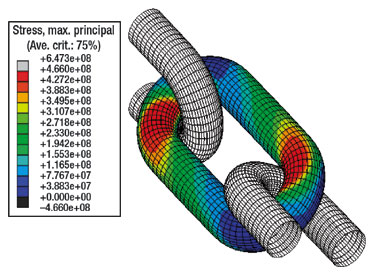 |
Fig. 2. As chain links turn against each other, the contact area becomes oval, then separates into two distinct patches (after Ridge et al. 2006).
|
|
This study developed predictive tools to identify torque in twisted chain, as load is applied along the chain’s axis.
EXTENDING MODU MOORING
Setting mooring lines once a MODU arrives on station at a new drillsite is an expensive operation, since the rig is idle until its position is stable. Shell reduced idle time from 7 – 8 days down to 1 – 2 days through the use of Pre-Installed Mooring (PIM).5
PIM uses two sets of mooring lines. While the fist set is in use, the second set can be preset at the next wellsite. Using two sets, a MODU can be put under tow to the next site quickly by disconnecting and buoying-off PIM lines, rather than wait for full mooring system retrieval.
Benefits of this approach include: reduced hookup time, reduced mooring disconnect time, less downtime from weather and less storm-safe time.
Shell sought to reduce the PIM system’s capex and opex while reducing the system’s watch circle radius using polyester ropes. These replaced the standard steel ropes used in their first-generation system, allowing a reduction in MODU deck load and an extension of MODU deepwater drilling capability.
The PIM line typically uses these components, Fig. 3:
 |
Fig. 3. Shell’s second-generation PIM system is a steel wire and polyester rope combination with different line segments for up to 10,000 ft water depths (after Shu and Loeb 2006).
|
|
- 3-9/16-in. diameter connecting chain with chaser stopper
- One 50 kip inline submersible buoy with 100 ft of 3-9/16-in. diam. R4 chain
- Polyester ropes (800 tonne MBL, 6.9-in. dia. with segment lengths for different water depths)
- 6-strand wires (3-9/16-in. dia. X 2,000-3,500 ft)
- Suction pile anchors with 51 ft of 3-9/16-in. diam. forerunner wire and Delmar subsea connector.
Rig wire payout varies from 1,400 ft to 2,200 ft depending on the anchor’s water depth, mooring line scope or other sea floor constraints.
Shell installed its new system on the Transocean Deepwater Nautilus in 2001, which allowed the vessel to drill in the GOM in 7,500 ft to 9,100 ft water depth. The vessel and polyester PIM survived Hurricanes Isidore and Lili in 2002, but the system’s mooring wires failed during Hurricane Ivan.
Shell’s experience shows that torque-balanced polyester ropes can extend MODU’s mooring capability and that mooring pattern optimization may improve MODU hurricane survivability.
Of critical importance is their finding that the filter on polyester ropes protected the rope’s load-bearing core from mud. This suggests that ropes with a 20-micron or tighter filter can be pre-laid on the seafloor without a problem.
NEW MATERIALS
Carbon Fiber Reinforced Plastic (CFRP) has been used for civil engineering applications such as pre- and post-stressed concrete and cable-stayed bridges. Now, companies are exploring their application to offshore mooring.
CFRP is being considered for ultra-deepwater MODU mooring lines because of its potential for substantial weight reduction and increasing payload for the same diameter as an equivalent steel rope. CFRP have the potential to use steel-line handling vessels with little or no modification.6
Polyester lines (ropes) have larger diameters than steel lines and require dedicated vessels for installation, which increases mooring deployment costs. To overcome these problems, CFRP rods offer the strength and diameter of steel, coupled with the durability and lighter weight of polyester systems.
Aker Kvæner and ConocoPhillips have applied this technology, to tension-leg platform tendons, and produced a spoolable tether, Comptether. In addition, another consortium of Freyssint, Soficar and Doris Engineering has produced a tendon design that uses High Modulus Polyethelene (HMPE). This design is developed from cable-stayed bridge tendon technology.6
Synthetic rope analysis is complicated by visco-elastic behavior. Its extension and modulus are a function of time and loading history and residual strain remains as viscous flow.
Synthetic rope systems need weight on the end of the mooring line so that anchor forces are tangential to the seabed. This requires steel line or chain at the base of drag anchor or catenary systems. Abrasion and wear issues also call for durable material on the seabed.
The proposed design would produce a MODU mooring system using pultruded (pulled and extruded) CFRP rods in a spiral bundle. The design has seven parallel rods as a central core around which a helical core is wound. The layers are torque balanced by varying the direction and lay angles of different layers. While steel line spiral strand is not considered reelable, CFRP is half the stiffness and can be reeled.
The industry is making significant strides in solving the problems of storm loads and deeperwater mooring systems. Better modeling, combination line systems and new materials are expanding the operating envelope for MODUs, while preparing for permanently fixed production systems that can weather the strongest storms. 
 |
Fig. 4. CFRP in different forms (red) are stronger than steel, polyester and other fibers used for mooring (after Jackson et al. 2006).
|
|
LITERATURE CITED
1 Balint, S. W., and D. Orange, “Panel discussion: Future of the Gulf of Mexico after Katrina and Rita,” OTC 18410, presented at the Offshore Technology Conference in Houston, TX, May 1 – 4, 2006.
2 Patton, C. G., C. J. Carra and P. Sincock, “Investigation of sway/ yaw motions of deepwater FPSOs,” OTC 18039, presented at the Offshore Technology Conference in Houston, TX, May 1 – 4, 2006.
3 Davies, P., P. Bouquet, M. Conte and A. Deuff, “Tension/ torsion behavior of deepwater synthetic mooring lines,” OTC 17872, presented at the Offshore Technology Conference in Houston, TX, May 1 – 4, 2006.
4 Ridge, I. M. L., R. E. Hobbs and J. Fernandez, “Predicting the torsional response of large mooring chains,” OTC 17789, presented at the Offshore Technology Conference in Houston, TX, May 1 – 4, 2006.
5 Shu, H. and D. A. Loeb, “Extending the mooring capability of a mobile offshore drilling unit,” OTC 17995, presented at the Offshore Technology Conference in Houston, TX, May 1 – 4, 2006.
6 Jackson, D., B. Shepheard, E. Kebadze, R. Teles, R. Rossi and R. C. Conçalves, “CFRP mooring lines for MODU applications,” OTC 17353, presented at the Offshore Technology Conference in Houston, TX, May 2 – 5, 2005.
|

