Seismic Technology
Imaging beneath basalt using an over-under towed-streamer configuration
Acoustically fast, highly absorptive overburdens, such as those found in the Faeroes basin, can be better imaged using vertically paired streamers and vertically with paired sources.
David Hill, Leendert Combee and John Bacon, WesternGeco
In conventional towed-streamer marine acquisition, shallow sources and cables increase the high-frequency content of the seismic data that is needed for resolution. However, this arrangement attenuates the low frequencies needed for stratigraphic and structural inversion. Towing shallow also makes the data more susceptible to environmental noise.
Deep sources and deep cables enhance low frequencies, attenuate high frequencies, and the data has a higher signal-to-ambient-noise ratio due to the more benign towing environment. A conventional towed-streamer survey design, therefore, attempts to balance these conflicting aspects to arrive at a tow depth for sources and cables that optimizes bandwidth and signal-to-noise ratio for a target depth or two-way traveltime, often at the expense of other shallower or deeper objectives.
An over/ under, towed-streamer configuration acquires seismic data with cables towed in pairs at two different cable depths, with one cable above the other. The depths of these paired cables are typically much deeper than would be used for a conventional towed-streamer configuration. In conjunction with these paired cables, it is possible to acquire data with paired sources at two differing source depths. Again, the depths of these paired sources are typically significantly deeper than would be used for conventional towed streamers.
Data from the over/ under streamer configuration is combined in data processing into a single dataset that has the high-frequency characteristics of conventional data, recorded at a shallow towing depth, and the low-frequency characteristics of conventional data, recorded at a deeper towing depth. This combination process is commonly referred to as deghosting.
There are benefits to over/ under data compared to conventional data:
- Significantly broader signal bandwidth with low-frequency content gives deeper penetration, and therefore, improved imaging beneath basalt, salt and other highly absorptive overburdens. Moreover, the bandwidth extension to lower frequencies makes seismic inversion less dependent upon model-based methods.
- If the over/ under cable pair had a vertical separation equal to the shallow tow depth of a conventional high-resolution configuration (typically less than 6 m), and the closely spaced over/ under cable pair was towed at depth (typically > 15 m), then the combined over/ under dataset would have the high-frequency content given by the vertical cable separation and the low-frequency content delivered by the deep tow depth.
- A simpler signal wavelet with the bandwidth extension to higher frequencies gives enhanced resolving power and allows for a more detailed stratigraphic interpretation.
- Higher signal-to-ambient-noise ratio is a consequence of the deeper towed-cable pairs.
- An extended weather window enables the deeper towed-cable pairs.
The potential future benefits of over/ under data are:
- Offering ocean-bottom-cable type multiple-attenuation schemes to towed streamer data
- Removal of sea-surface effects from 3D data, hence, improving 4D repeatability.
The over/ under acquisition concept has been known and understood since the mid-1980s. The technique was first proposed by Sønneland and Berg1 and first attempted by Geco-Prakla in the Barents Sea shortly thereafter. That attempt was not successful, as the two cables could not be kept vertically paired. Recent commercial applications of the over/ under technique have been made possible by the development of the steerable streamers. The control systems associated with these cables are capable of keeping them in horizontal and vertical alignment, one above the other, to within the small tolerance required for the method to work correctly.
The first commercial single-source depth and over/ under cable acquisition program was performed in December 2004. In 2005, over 3,500 km of over/ under data were acquired, with a high percentage having both over/ under sources and over/ under cables. In 2006, the evolution of the technology continued with the commercial application of the over/ under technique being extended to 3D.
OVER/ UNDER ACQUISITION
Figure 1 shows over/ under acquisition geometry, with paired sources at two different depths and paired cables at two different depths. The wavefield radiates out from the seismic source, not only traveling downward, but also upward. The upward-traveling wavefield is reflected back from the sea surface with an opposite polarity as the source ghost. The downward-propagating wavefield is reflected back from the subsurface to become an upward-propagating wavefield. The upward-propagating wavefield is also reflected back from the sea surface with an opposite polarity as the receiver ghost. The complex interference of the source and receiver ghosts causes notches in the amplitude spectra of the recorded seismic data. These notches are a key factor in restricting the bandwidth of the seismic data.
 |
Fig. 1. A 2D over/ under acquisition configuration.
|
|
The destructive interference occurs at frequencies given by:
| |
fnotch = Wvel / (2Cdepth × Cos(phi )) |
Eq. 1 |
where fnotch is the frequency at which the ghost notch occurs, Wvel is the water velocity, Cdepth is the cable depth, and phi is the emergence angle of the raypath normal to the expanding source wavefield, Fig. 2.
 |
Fig. 2. Amplitude spectra of ghost responses for a 7.5-m source depth and cable depths of 7.5 m, 15 m and 22.5 m. Constructive interference produces peaks in the spectra, while destructive interference creates notches.
|
|
The basic principle of the over/ under combination is to use the data recorded by the over/ under cables to separate the wavefield into up-going and down-going components. The up-going component is the primary wavefield; the down-going component is the ghost reflection from the free surface. The up-going wavefield has a simpler seismic wavelet, its spectrum is free from ghost notches, and it has a much broader bandwidth than that achieved from a conventional towed-streamer marine acquisition configuration.
Various methods have been proposed to achieve deghosting using an over/ under acquisition configuration.2,3,4 In the case history cited below, the Posthumus3 technique was used for both the over/ under cable and source combinations. This method is relatively robust, but requires the explicit specification of the sea-surface reflection coefficient, source depth, cable depths and water velocity.
The amplitude spectrum of the data resulting from the over/ under deghosting using this technique is a weighted sum of the amplitude spectra of the over and under datasets, where the weights maximize the signal contribution from each of the respective datasets into the summation. The resulting deghosted spectra have the ghost notches removed and the spectral bandwidth extends to a maximum frequency given by the first coincident ghost notch or harmonic, common to all source and cable depths. The deghosted data spectra from an over/ under cable combination with cable depths of 15 m, and 22.5 m, is broader than the data spectra from a conventional towed-streamer configuration, where the cable is towed at a depth of 7.5-m equivalent to the over/ under cable separation, Fig. 2.
A 2D over/ under acquisition geometry (Fig. 3) comprises four cables: the over/ under cable pair and one cable towed either side of the over/ under cable pair to provide the acoustic positioning network necessary to locate the cable pairs. The published deghosting techniques require that the wavefield recorded by the over cable be a time-delayed version of the wavefield recorded by the under cable. Operationally, this translates into keeping the over and under cables at constant depths, with a constant vertical separation and no lateral separation. Consequently, the main requirement of an over/ under cable acquisition system is to align the cables vertically above each other and then maintain their alignment in the vertical plane throughout the survey.
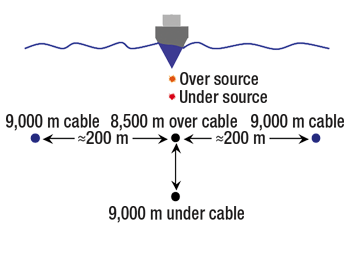 |
Fig. 3. A 2D over/ under acquisition geometry.
|
|
Figure 4 shows steering performance for a typical over/ under acquisition. The plot on the left illustrates the inline difference between corresponding streamer steering devices on both the over and under cables. At the head of the cable (nearest the vessel), the inline difference between corresponding steering device positions on the over/ under cable pair is zero. However, the inline difference increases as a function of steering device position along the two cables.
For operational reasons, the under cable is slightly longer that the over cable such that the tailbuoys, floating freely from the ends of both cables, do not tangle during line turns. As a consequence of their differing lengths, the under cable is under higher tension than the over cable, and therefore, stretches slightly more. Also, small differences in ballasting may contribute to in-line position differences. However, the short 3.125-m group interval within the streamer allows for the sensor positions of over and under cables to be properly vertically aligned during data processing, thereby removing any inline positioning difference.
The plot in the center of Fig. 4 illustrates the crossline difference between corresponding steering device positions on both the over and under cables; in this instance, the crossline positional difference is significantly less than 5 m. The cumulative crossline distribution curve is the right plot of Fig. 4, and for about 84% of this sail line, the crossline separation is 4 m or less. Equivalent diagnostics from over/ under surveys acquired to date indicate that this level of steering performance is the norm, well within the tolerance required for the over/ under technique to work.
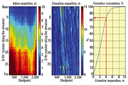 |
Fig. 4. Inline and crossline positioning difference diagnostics for a single 2D over/ under line taken from a recent over/ under survey.
|
|
Almost all of the depth information for all three cables falls with ±0.5 m of the desired cable depths, Fig. 5. This is well within the standard acquisition specifications of a conventional towed-streamer operation and demonstrates that lateral cable control is not gained at the expense of cable depth control.
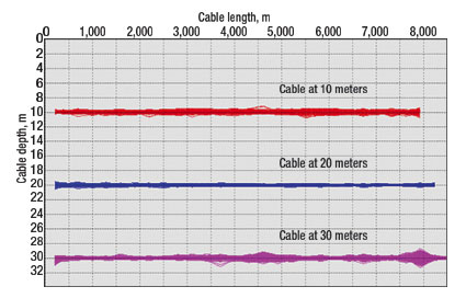 |
Fig. 5. Cable depth information from each steering device for an experimental three-cable over/ under configuration. In this figure, the cable depth information for 2,500 shots is plotted superimposed on top of each other.
|
|
In summary, the directional deghosting of data recorded using both over/ under sources and over/ under cables delivers the complete removal of ghosts associated with the source and receiver. This removes the band-pass filtering effects at the low and high frequencies caused by constructive and destructive interference; hence, delivering data with a higher bandwidth. The bandwidth of over/ under data now becomes governed by the bandwidth of the source itself, absorption at the high-frequency end of the spectrum, and the instrument filters at the low-frequency end of the spectrum.
CASE HISTORY
In the autumn of 2005, the Western Pride completed a large regional 2D over/ under survey for Chevron. The survey was conducted in the North Atlantic east of the Faeroe Islands and west of the Shetland Islands. The survey objective was to provide an improved seismic image of the subsurface beneath the basalt. As stacked basalt flows typically exhibit a low-pass character to seismic waves,5 successful sub-basalt imaging relies on technologies that extend the useable seismic bandwidth toward the very low frequencies. Over/ under deghosting is one such technology.
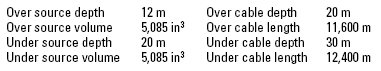
The maximum frequency expected using this particular acquisition configuration (Table 1) is about 75 Hz, where we have the first coincident ghost notch. This upper limit to the bandwidth is more than sufficient for the deep imaging objectives of this particular survey. But, if a higher upper frequency was required in a different circumstance, then this could easily be achieved by changing the separation of source and cable depths such that the first common notch moved toward the higher frequencies.
| TABLE 1. West of Shetlands over/under acquisition configuration |
 |
|
Over/ under data processing. The key steps in an over/ under data processing sequence are outlined below. The over/ under combination takes place very early in the data processing sequence on prestack data, in order to correctly compensate for the directional properties of the source and cable ghosts. As Eq. 1 shows, the ghost notch frequency for a given cable depth is a function of the angle of the raypath normal to the expanding wavefield.
The key data processing steps in an over/ under data processing sequence are:
- The field data records at a 3.125 m group interval
- Data regularization
• Align the receivers in the over cable with the receivers in the under cable
- Over source and over/ under cable combination
• The over source ghost remains in this dataset, but the directional cable ghost is completely removed
- Under source, over/ under cable combination
• The under source ghost remains in this dataset, but the directional cable ghost is completely removed
- Over/ under combination of over source and under source
• The data from Steps 3 and 4 are now combined, resulting in the complete removal of the directional source ghost
- After the over/ under combinations are compete, both the source and receiver ghosts have been removed. The data processing sequence then follows a more conventional route, but parameterized in such a way as to maximize the benefits of the enhanced bandwidth delivered in the over/ under combination steps.
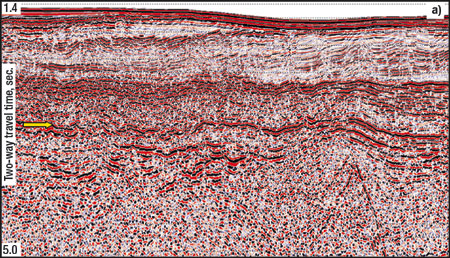
Comparative results. Figure 6a is the migrated image from the over source at a depth of 12 m and the over cable at a depth of 20 m, which is equivalent to data recorded by a conventional deep towed-streamer acquisition configuration. Figure 6b is the corresponding migrated image from the fully deghosted data from the over/ under source and cable combination. Both datasets are processed using identical parameters; they are migrated with the same velocity field, stacked with the same velocity field and have the same post-migration processing applied. Indeed, the prestack data used to generate the migrated image in Fig. 6a are one of the key components in the over/ under combination that produced the image in Fig. 6b.
 |
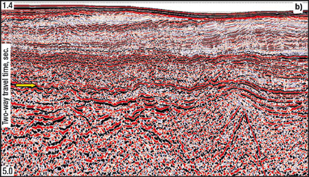 |
Fig. 6. a) Kirchhoff prestack time-migrated image of the data recorded by the over source at a depth of 12 m and the over cable at a depth of 20 m. Top of basalt is highlighted by the yellow arrow. b) Kirchhoff prestack time-migrated image of the fully deghosted data from the over/ under source and cable combination.
|
|
As seen in Fig. 6, the combined over/ under dataset is far richer in the lower frequencies compared to the deep towed-streamer acquisition configuration. The image quality beneath the basalt on the data from the over/ under combination is far superior to that from the conventional deep towed-streamer acquisition configuration. Consequently, the structural interpretation of the data from the over/ under combination can be made with much more confidence. 
ACKNOWLEDGEMENT
The authors thank Chevron, and in particular, Kevin Davies and Gary Hampson of Chevron, for permission to publish some of the data examples, and John Sansom, Philip Christie, Alan Strudley, Steve Pickering, and Ed Kragh of WesternGeco.
LITERATURE CITED
1 Sønneland, L. and E. Berg, “A new method for separating wave fields into up- and down-going components,” Abstract B-46, 47th Meeting, European Association of Exploration Geophysicists, Extended Abstract, 1985.
2 Sønneland, L., Berg, E., Eidsvig, P., Haugen, B. F. and J. Vestby, “2D de-ghosting using vertical receiver arrays,” 56th Meeting, Society of Exploration Geophysicists, Expanded Abstract, pp. 516 – 519, 1986.
3 Posthumus, B. J., “De-ghosting using a twin cable configuration,” Geophysical Prospecting, Vol 41, pp. 267 – 286, 1993.
4 Amundsen, L., “Wavenumber-based filtering of marine point-source data,” Geophysics, Vol. 58, pp. 1335 – 1348, 1993.
5 Ziolkowski, A., Hanssen, P., Gatliff, R., Jakubowicz, H., Dobson, A., Hampson, G., Li, X., and E. Liu, “Use of low frequencies for sub-basalt imaging,” Geophysical Prospecting, Vol. 51, pp. 169 – 182, 2003.
FURTHER READING
Parkes, G. and L. Hatton, “The marine seismic source,” D. Reidel, pub, ISBN 90-277-2228-5 SEG 4, 1986.
|
THE AUTHORS
|
 |
David Hill is a Principal geophysicist with WesternGeco in Gatwick, with expertise in seismic survey design, seismic acquisition and data processing. He has been with WesternGeco since 1999, acting primarily as a technical advisor for the European and West African data processing centers. For the 10 years prior to joining WesternGeco, he served as an operational geophysicist for Amoco UK, with responsibilities for both seismic acquisition and data processing. Before joining Amoco, he worked for Western Geophysical. Mr. Hill holds an honors degree in geophysics from the University of Liverpool.
|
|
 |
Leendert Combee has been with WesternGeco for 14 years and is geophysical advisor for marine technology development in Oslo, Norway. He has MSc and PhD degrees in Electrical Engineering and Applied Geophysics from Delft University in the Netherlands.
|
|
 |
John Bacon works as an area geophysicist for WesternGeco and is based in the UK. John has 27 years of seismic data processing experience, including the technical supervision of many seismic projects involving Q technology since 2001. Recent Q technology projects include those involved with wavefield separation enabled by the over-under acquisition method. John began a career in geophysics following graduation in 1979.
|
|
|

