Casing While Drilling
Casing directional drilling is ready to go offshore
Success with casing while drilling in onshore wells has provided the confidence to extend system capabilities to directional and offshore wells.
Brett Borland and Rick Watts, ConocoPhillips; Tommy Warren, Tesco Corp.; and Bill Lesso, Schlumberger
In recent years, casing while drilling (CWD) has proven its merit in reducing costs while gaining new efficiencies. The benefits have been well documented, including reduced trips, removal of drilling flat times, the ability to drill difficult transition and depleted zones, and facilitation of underbalanced drilling.
A natural extension of CWD is casing directional drilling (CDD), which began to emerge in late 2003, albeit with a few nagging problems. Successful field tests last year have solved those problems for onshore usage. Now, a cooperative effort at Eldfisk field, Norway, between ConocoPhillips, Tesco and Schlumberger will strive to prove up the same technology for offshore usage.
TAKING CWD OFFSHORE
CWD has demonstrated operational time savings of about 15% in straight hole applications versus normal drill pipe drilling. This benefit is also expected to apply to CDD in an offshore environment. The comparison is based on normal operating times for each case. The expected bit rotating hours from drilling below the previous casing shoe until section TD is reached for CWD, are sometimes more, but generally not more than 10% over that experienced with drill pipe. Eliminating the need to pick up drill pipe, condition the well, and trip out of the hole to run casing can save substantial time. Routine changes for bits, underreamers and MWDs will also save time.
Most of these benefits are realized by minimizing the impact of formation-related problem time. Improved hole cleaning in the 10-3/4-in. section should eliminate problems in casing washing to bottom and should improve cement jobs. This is due to the mud’s good condition, because the casing has not been run in a separate trip. Problems with fluid losses and shale stability in the 7-3/4-in. section should be reduced, due to the smear effect. Even where losses occur with the casing on bottom, drilling to the casing point can be achieved, and cementing can be done, without having to stabilize the hole. Achieving benefits at Eldfisk, similar to those seen in straight hole casing drilling, provides the potential to reduce drilling times by five to seven days per well.
If the smear effect is as effective in chalks as it is in sandstones, then a casing string may be eliminated. Drilling times will be reduced further, allowing one to two more wells to be drilled per year. In the longer term, successful CDD will allow fit-for-purpose rigs and casing drilling-enabled rigs built for offshore use. The expectation is that, just as for land rigs, a specific rig for offshore will be smaller and require fewer staff. In the meantime, the effort required to convert the Norwegian rig has stimulated efforts to develop a portable kit that easily allows retrievable casing drilling systems to be used on conventional offshore rigs.
RETRIEVABLE VS. NONRETRIEVABLE CWD
Casing can be used as all or part of the drillstring in a number of ways, but the systems can be categorized as either retrievable or nonretrievable. A nonretrievable system includes both liner drilling applications and applications with full strings of casing, where a fixed bit is used for drilling. The bit may be drillable, or it may be a conventional bit that is left in the hole at TD.
Retrievable systems allow the bit and bottomhole assembly (BHA) to be changed without tripping the casing. Use of a retrievable system is the only practical choice for directional wells, because of the need to recover the expensive directional drilling and guidance tools, the need to have the capability to replace failed equipment before casing point, and the need for quick and cost-effective access to log the formations below the casing shoe.
A retrievable CWD system has downhole and surface components that enable standard oilfield casing to be used as the drillstring, so that the well is simultaneously drilled and cased, Fig. 1. The BHA can be changed without tripping casing. A wireline-retrievable drilling assembly is suspended in a profile nipple near the bottom of the casing. The BHA’s top component that facilitates the attachment to the profile nipple is the drill lock assembly (DLA). The casing is rotated from the surface, and the drilling fluid is circulated down the casing ID and back up the annulus.
 |
Fig. 1. Casing drilling equipment deployed, from top to bottom: Split block, standard swivel, top drive and casing drive system. This rig is drilling with 7-5/8-in. casing.
|
|
The drilling assembly includes an underreamer and terminates with a pilot bit, but it may include other conventional drillstring components, such as a mud motor, stabilizers, drill collars, MWD or LWD tools. The pilot bit is sized to pass through the casing, and the underreamer opens the hole to a size similar to what is normally drilled to run the casing. For example, a 6-1/4-in. pilot bit and an 8-7/8-in. underreamer are commonly used while drilling with 7-in. 23-lbm/ft casing. The underreamer can be located immediately above the bit or above other components run in the pilot hole.
A top drive rotates the casing for drilling and is used to torque the connections. The casing string is normally rotated for all operations except slide drilling, with a motor and bent housing assembly for oriented, directional work. A motor may also be used to rotate the BHA, when an RSS is used. This allows the casing rotation speed to be minimized.
The casing is attached to the top drive via a quick-connect system without screwing into the top casing connection. The hardware includes a slip assembly to grip either the exterior or interior of the pipe (depending on pipe size), and an internal spear assembly that provides a fluid seal to the pipe. It is operated with the hydraulic top drive control system. This quick-connect system speeds casing handling and prevents thread damage.
Single casing joints are picked up from the pipe rack and placed in the V-door. They are then picked up with a single-joint elevator attached to the system. The joint is hoisted as the top drive is raised, stabbed into the top of the casing string in the rotary table, gripped by the quick-connect dies, torqued to specifications, and then drilled in a conventional manner.
These retrievable drilling assemblies have been used to drill more than 1,000,000 ft (300 casing intervals) in commercial wells with retrievable and re-runable tools. ConocoPhillips has drilled about 80% of these wells. A relatively small number of these casing intervals, 13, has been directionally drilled with retrievable steerable motor assemblies, or RSS’s, while drilling with 7-in. and 9-5/8-in. casing.
Sufficient experience has been gained while drilling commercial vertical wells to determine the tools’ reliability and ruggedness, and to quantify the advantages of retrievable drilling assemblies. However, CDD is still in its infancy. Optimized practices and procedures have not been completely developed.
CWD HARDWARE
The hardware used in CWD operations over the past five years has proved to be robust and reliable. Several directional wells have been drilled successfully with casing, using positive displacement motors (PDMs), but the drilling efficiency was significantly degraded in most of them. Accordingly, two wells were drilled with a new configuration that utilizes a rotary steerable system (RSS) to improve efficiency when drilling with casing.
Combining an RSS with CWD operations seemed to be a natural way to eliminate the major weaknesses in motor BHA designs. Rotary steerable systems had not previously been used for CWD, because both are new technologies. CWD was developed in land operations, while RSS’s have been popular for offshore projects.
ConocoPhillips has drilled more than 120 wells in the Lobo trend of South Texas since 2001, using the new technique. As part of a demonstration project to accelerate the technology to offshore applications, the company drilled two of the aforementioned wells with an RSS. The first was an operational test conducted by drilling vertically with the RSS. The second well was a full, directional test with a build to 29°, and then a drop to vertical, including a 100° directional turn.
CDD PROBLEMS WITH MOTORS
Because casing is larger in diameter than drill pipe, it tends to elongate much more than drill pipe when the motor begins to pressure up. This provides a positive feedback system that makes motors with steep torque/ pressure curves difficult to run while drilling with casing.
A number of problems were experienced in the original attempts to conduct CDD with bent housing mud motors, Fig. 2. To fit into the 7-in. casing, the steerable motor used had to be one size smaller than would otherwise be required. This caused poor ROP performance, resulting in inefficiencies and more expense. For instance, one well in the Lobo trend of South Texas took 18.2 days to drill to the intermediate casing point, when a comparable, trouble-free vertical well might have taken 8.5 days. These problems are less pronounced in 9-5/8-in. and larger while-drilling casing, when the mud motor power is less restricted.
 |
Fig. 2. A cascading effect adds to the increased frequency of motor stalls in CDD. When the motor begins to stall, pressure builds, causing elongation in the casing. This pushes more weight-on-bit, accelerating the stall.
|
|
AN RSS SOLUTION
Early CWD applications provided an opportunity to develop surface equipment and procedures to handle casing, equipment to protect casing and connections while drilling, and a robust and reliable system for locking and unlocking the BHA to the casing.
Initial application and subsequent evolution of system components were focused on onshore vertical wells, where the cost of learning could be tolerated. This development work identified field applications that would benefit from reducing lost circulation and eliminating problems with drilling depleted zones. These wells were mostly vertical, eliminating operational complexity. CWD has developed to the point where operations are routine, and the hardware operates as reliably as other rig systems.
Meanwhile, RSS’s were being developed to solve problems in wells at the other end of the scale. It had become difficult to use PDM steerable systems in extended-reach directional and horizontal wells, where the ratio of displacement to TVD is high. Orienting a motor for a directional correction took up to six hours at MD’s of 25,000 ft or more. RSS’s, while very expensive, eliminated orientation or sliding operations and made it possible to drill wells, such as the record-breaking Wytch Farm well, M-16, to 37,000 ft MD.
As RSS’s improved, became more durable, and costs went down, they were applied to less demanding offshore projects. At first, RSS’s were applied on deepwater wells. As the efficiency in directional operations became well known, directional operations moved away from motors to RSS’s in the North Sea, the Gulf of Mexico shelf and other offshore developments. RSS’s are now used in about 60% of directional wells offshore.
Success in reducing losses in historically problematic formations has sparked interest in applying CWD to similar situations offshore. The difficulties in CDD posed a roadblock. Directional operations with PDMs in smaller hole sizes were not effective. RSS’s were, therefore, an obvious avenue to investigate. There was very little overlap in logistics and methodologies for merging these two technologies. At this point, participants from ConocoPhillips, Tesco and Schlumberger pooled resources to test this approach to CDD.
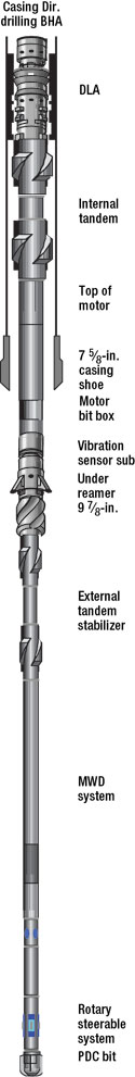 |
Fig. 3. The CDD BHA design used in the 7-5/8-in. test has a stick-out of 85 ft, while a vertical BHA has a stick-out of only 15 ft.
|
|
TESTING THE RSS IDEA
Applying an RSS to CDD was not as simple as shipping a set of tools. These questions arose:
- Will there be difficulties with stiffness ratios and vibrations?
- What will be the directional control and tendency?
- How can the rig supply higher revolutions per minute (rpms) for effective RSS use?
- How will the flow and pressure requirements of RSS and MWD systems impact CDD operations?
Most of the wells in the Lobo trend development are vertical. The well proposed to test this approach was no exception, but a unique opportunity presented itself. The proposed location was about 1,200 ft to the south of a well that was drilled in March 2004. The team proposed to use the old well surface location and drill an S-shaped trajectory over to the new well’s target location. While this would save the cost of building a new location, the additional costs of a directional well are more than three times the location cost. This was the best option to test RSS’s in a full directional trajectory, because a directional well was not planned for the remainder of 2004.
A review of the existing pad showed that the remaining open space for the rig put the well in nearly a direct line between its target location and the rig. This location added complications to the trajectory design. The basic plan called for a build to 29° and then a drop into the target 1,200 ft away. Now, the trajectory would have to be routed around the existing producing well to avoid colliding with it. The new well would kick off along an azimuth that was 40° east of the target azimuth, build to 29° and start a 100° turn to the right. During the later stages of the turn, the drop would be initiated, bringing the well into the target. This profile resembled those used on large, multi-well offshore platforms.
The BHA design for the 7-in. section had several innovative features, Fig. 3. It is 112 ft long, with an 85-ft stick-out below the shoe of the 7-in. casing. Starting from the top, inside the casing, is the DLA. Below the DLA is a tandem casing stabilizer. This has two stabilizer blade sections that are gauged to the internal drift diameter of the 7-in., 23-lbm/ft of 6.26 in. This stabilizer is designed to take most of the drilling vibrations away, reducing DLA wear.
The mud motor is below the tandem casing stabilizer and is relatively large, with a 6-in. diameter. The motor allows drillstring rotation to be lowered when dealing with vibration issues. The motor adds the rpms back into the BHA and bit to maintain a good ROP. The probability of whirl meant that surface cycles could be limited to 50 rpm. The motor would add 100 turns to the drillstring, bringing it to the optimum rpm range.
The underreamer was placed directly below the mud motor. This opened the pilot hole to 8-7/8 in. When the pumps were off, the underreamer’s arms collapsed, so that the tool’s maximum diameter was slightly less than 6-1/8 in. To be retrievable, all BHA components had to be smaller than the casing’s internal diameter.
Drilling operations started in the 7-in. section at 1,278 ft. The proposed kickoff point was 2,100 ft. The RSS was programmed for verticality mode. MWD telemetry was strong, and attenuation was 40% to 50%, instead of the expected 90%. Surveys indicated that the wellbore was nearly vertical. At kickoff, the RSS was programmed for three sets between 135° and 160° magnetic toolface at 60%. Therefore, the well kicked off at 150° (30° east of south) at 60% of the RSS’s full thrusting capabilities.
Magnetic directions or toolface are typically used until the wellbore is at a greater than 5° inclination. Once this was accomplished, the RSS was set to an 18° gravity toolface at 60%. This specified direction was 18° right of straight-up in the well (gravity is down) at 80% of full thrust. The well continued the build with a slight turn to the right. The build was accomplished as planned. Figure 4 shows the first six sets in drilling the kickoff.
In the 7-in. section of the directional well, 132 joints were CDD’d. This compares closely with the 128 joints of casing drilled in the nearby vertical well. The ROPs on a joint-by-joint basis for the directional well were slightly less – by about 10% – than the ROPs in the vertical well.
TESTING THE IDEA FOR OFFSHORE SITES
There were two wells drilled in 2004 that combined RSS and CWD systems to demonstrate that CDD was possible. These were not exhaustive tests, but they did prove that combining an RSS with 7-in. pipe for CDD was viable. The key question is, “Can the straight hole benefits realized in the Lobo field be transferred to directional drilling offshore?”
The next step in CWD is to develop the tools and procedures to drill complex directional wells. With full directional capability, offshore development applications become possible. However, to make CDD a reality, significant technical challenges must be overcome. Adopting this new drilling technology into a producing asset is a challenge beyond just the technical aspects. Implementing the technology may require rig/ platform equipment modifications that impact production, and the initial wells may take longer to drill as the learning curve develops.
To reduce the risk associated with implementation, a wellbore profile similar in complexity (hole angle, build rate, depth) to a well to be drilled off of the Eldfisk B platform offshore Norway was drilled with 10-3/4-in. and 7-3/4-in. casing. The equipment used in these field trials included the same tools that would be used in Norwegian operations. This was done to mirror the platform activity that would be necessary to execute the project. Safety and training were also integral components.
The surface system selected for the Norwegian wells provides the most safety and flexibility, but it requires significant equipment installation on the rig. Surface equipment includes the wireline unit and crown sheave, wireline BOP system, split traveling block and casing drive system. All of these items must be certified to Norwegian regulatory specifications.
The portable casing drive system used for connecting the top drive to the casing without making a threaded connection is routinely used for offshore casing running jobs and is already certified. It hangs below the top drive and can grip the pipe to apply full hookload and torque to the casing segment to both make up the connection and to drill with the casing. An internal seal assembly provides the fluid seal for circulation.
The split traveling blocks are readily available and relatively easy to change out on the rig. On the other hand, providing the wireline unit is more problematic – only a single wireline unit has been built with adequate wireline hoisting power. The prototype traction winch was used for the testing described below, but a new unit was designed and built in Norway to facilitate obtaining the required certification. This unit has the capability to pull up to 40,000 lbm with a 7/8-in. braided cable while providing sufficient control of the wireline feed to use in making up tools at the surface and manipulating the downhole tools. Power will come from an existing open-loop hydraulic system.
The wireline unit incorporates a traction winch, designed to allow high-tension loads on the wireline while also spooling the wire properly. A key design constraint is that it be able to spool off and spool on the wire at any combination of high/ low speed and high/ low tension.
This capability is critical for providing efficient operations under the wide range of conditions for handling downhole equipment, while making up on the surface, and running into and out of the well. Special considerations also must be taken in low-tension operations to effectively spool the wire into the well as BHAs are pumped into highly deviated casing sections.
The cost of offshore operations and the inefficiencies associated with first uses (learning curve) of a new technology, such as CDD, drives most first-time applications to being tested on land operations.
An additional problem arose in testing 10-3/4-in. and 7-5/8-in. CDD. The 7-5/8-in. equipment was designed and built before the 10-3/4-in. hardware, and the team wanted to prove the tool design before building larger tools. An interesting option presented itself. A horizontal well had previously been drilled at the test facility and cased with 13-3/8-in. casing for use in testing completion and production hardware. Using this existing wellbore allowed the 7-5/8-in. casing tools to be tested at high angles before the 10-3/4-in. tools were built. This type of flexibility made it possible to drill the test in reverse order; testing the smaller tools before the larger tools.
7-5/8 CDD TEST
The 7-5/8-in. CDD test took place at the test facility last July. The objective was to test the new equipment at various hole inclinations up to horizontal. The existing well built to horizontal at about 3°/100 ft at a TVD of 2,200 ft. All of its 600 ft of horizontal section had 13-3/8-in. casing. Set/ retrieval tests were scheduled at 0, 45 and 90 degrees inside the existing casing.
 |
Fig. 4. The first six RSS toolface instruction sets in the kick-off of one of the test wells.
|
|
 |
Fig. 5. A trajectory plot of the horizontal well that was used in the 7-5/8-in. CDD test. Also shown are the four set/ retrieval operations at various angles that were critical to the test.
|
|
After the three non-drilling, in-casing set/ retrievals, 850 ft of new hole were drilled horizontally to test the complete system under actual drilling conditions. A full CDD BHA was used, incorporating a 4-3/4-in. RSS. It drilled a 6-1/2-in. pilot hole and utilized a 9-7/8-in. under-reamer. No change in hole inclination was tested, but a directional program of first turning the well to the right at 1.0°/100 ft and then to the left at 3.0°/100 ft tested the directional performance of the BHA.
TD was called at 4,668 ft after drilling 842 ft in 31 hrs. The wireline was run, and the BHA successfully retrieved.
A downhole vibrations sensor sub was run above the underreamer. It recorded lateral and torsional accelerations. Lateral vibrations data for the run are shown in Fig. 6. Shocks were higher than expected, but they tapered off during the run. These shocks did not damage BHA components. Recent developments in RSS’s have increased their robustness. A full inspection of the tools showed that the shocks did not damage them. But, the small-diameter, external BHA used in CWD is still susceptible to excessive vibrations and shocks.
 |
Fig. 6. Lateral vibrations data from the RSS (orange) near the bit and from a vibration sensor sub (green) located above the underreamer. Vibrations decreased as the test progressed.
|
|
10¾ CDD TEST
The 10-3/4-in. test took place last November at the test facility, where a well has 13-3/8-in. casing set vertically at 2,000 ft. After establishing the cement plug at the 13-3/8-in. shoe for sidetracking, the well was directionally drilled with first a low build rate of 0.5°/100 ft, and then a higher 3.5°/100 ft.
The BHA design was similar to those used in the 7-5/8-in. test last July. An RSS and an MWD were used for directional control in the pilot BHA. A straight motor was placed above the underreamer to supply downhole rpms. Downhole vibration measurements were transmitted up-hole in real time from the MWD tool.
Shock counts were also recorded downhole in the RSS. Additionally, three drilling research sensor packages were placed in the BHA – one above the underreamer and two below it, between the MWD and RSS. Downhole recorded measurements included annular pressure; lateral, axial and torsional shocks; axial speed; torque; and weight-on-bit. Two BHA’s were used to test differences in vibration response.
PLANS FOR ELDFISK
The next step is implementation offshore Norway. Two Eldfisk oil-producing wells are planned for 2006 utilizing CDD. Both wells will start from 13-3/8-in. surface casing set at about 1,200 ft. Plans include drilling with 10-3/4-in. to about 4,850 ft TVD, 5,100 ft MD, and 7-3/4-in. to about 9,600 ft TVD, 10,800 ft MD. These two wells will be drilled back-to-back and will share a common wellhead.
These field trials should demonstrate a learning curve similar to that in Lobo field. Further implementation of this technology will depend on the field trial outcome. However, plans are being made for CDD to become the preferred drilling method for remaining Eldfisk work. In the short term, remaining Eldfisk drilling will be done from recovered slots and will require the 10-3/4-in. casing to be drilled out of a pre- milled window off of a 13-3/8-in. whipstock.
ConocoPhillip’s two-well program at Eldfisk has the potential to usher in a new era of greater efficiency in offshore directional drilling that could bring a sea change in operators’ habits. Validation of this vision may come late this year. 
This article is derived mostly from SPE/IADC papers 92195 and 99248, presented at the SPE/IADC Drilling Conferences held in 2005 (Amsterdam, Feb. 23 – 25) and 2006 (Miami, Feb. 21 – 23), respectively.
|
THE AUTHORS
|
|
Brett Borland is manager of Drilling Technology for Conoco Phillips, having joined Conoco in 1990, following six years of experience with Oryx Energy Co., and three years with Sedco, a drilling contractor. He has extensive worldwide drilling operations experience on land and offshore. International areas include Abu Dhabi, Iran, Pakistan, Azeribaijan, Russia (Timan Pechora), Norway (North Sea and Barents Sea), the UK (North Sea and North Atlantic) and Congo. US areas include offshore California, Gulf of Mexico, Rocky Mountains, Oklahoma, West Texas, South Texas and North Dakota. Mr. Borland’s 20-plus years of drilling experience are broad and include horizontal/ directional, underbalanced drilling, HT/HP, well control, arctic drilling, and offshore operations on drillships, semisubmersibles, jackups, and platform rigs.
|
|
|
Rick Watts has worked on the Upstream Technology – Drilling Engineering and Operations (DEO) staff at ConocoPhillips as an engineering fellow since July 2003. He joined Phillips Petroleum in Bartlesville, Oklahoma, in 2000. Before joining the company, he worked 22 years for Arco. In 1978, Mr. Watts earned a BS degree in petroleum engineering from the Colorado School of Mines. He has worked for the company in Bartlesville and Perth. Responsibilities have included principal drilling engineer and Bayu Undan (Timor Sea) drilling manager.
|
|
|
Tommy M. Warren is the director of Casing Drilling Research and Engineering for Tesco Corp. He joined Tesco in 1999 after spending 26 years with Amoco in operations and drilling research. His research has led to the publication of 60 technical papers and 35 patents. Mr. Warren graduated from the University of Alabama with BS (1973) and MS (1976) degrees in mineral engineering and was selected as a University of Alabama Distinguished Engineering Fellow in 1994. He is active in SPE technical programs and served as chairman of the 1999 Annual Technical Conference and Exhibition. In addition, he was an SPE Distinguished Lecturer in 1998-99. Mr. Warren serves as chairman of the SPE Publications Coordinating Committee and is a member of the IADC/SPE Drilling Conference Program Committee. He was the recipient of the 1997 SPE Drilling Engineering Award, the 1985 SPE Cedric K. Ferguson Medal and the 1982 AIME/SPE Rossiter W. Raymond Award. He is the author of the casing drilling chapter for the upcoming SPE Advanced Drilling Engineering textbook.
|
|
| |
Bill Lesso is casing drilling advisor for Schlumberger Drilling & Measurements in Houston. He is working with ConocoPhillips on deploying casing directional drilling in Norway and China. He joined the company in 1976 as a field engineer in Dayton, Texas, after receiving a BS degree in mechanical engineering from the University of Texas at Austin. Since then, Mr. Lesso has held positions in wireline, well services, and drilling and measurements. He has managed horizontal and geosteering projects in Malaysia, the UK, Latin America and several US locations. He became involved in casing drilling after filling a visiting position at the Schlumberger Cambridge Research Center in England.
|
|
|

