Coiled Tubing Technology
Coiled tubing-conveyed fracturing system increases production
For use in shallow and intermediate depth gas completions, industry’s first resettable packer and bridge plug, run on coiled tubing, also reduces costs.
Ben Holmes, Baker Oil Tools
A recently developed coiled tubing-conveyed fracturing system (CTFS) was an advantage in completions at an East Texas field. Designed for use in shallow and intermediate gas wells, the FASTFrac system is based on the industry’s first resettable packer and bridge plug run on coiled tubing. The system enables multiple gas-producing zones to be completed in one trip in a live well. In its inaugural field run, it allowed field operator R. Lacy Services Limited to nearly triple production from previously bypassed zones while saving 10 days on fractures and flow testing over previous fracturing methods.
The new system saves time and money relative to existing techniques for specialized coiled-tubing workovers and new well completions. Its most appropriate application is selective fracturing of previously bypassed pay zones in shallow and intermediate gas wells. The system design allows CT conveyance in a tandem configuration that works within current lubricator restrictions, yet is capable of setting repeatedly as a combination retrievable bridge plug and treating packer. The plug and packer assembly is composed of a lower bridge plug, a hydraulic releasing tool and an upper packer. The packer uses an auto-jay to set and release, by cycling the coil string up and down the wellbore. A mechanical collar locator can be attached below the bridge plug to correlate the assembly with a wireline collar log to ensure proper depth placement.
The CTFS is short (about 12 ft), and can isolate any interval length and, if channeling occurs, the packer can be repositioned to regain isolation and continue treatment. The system’s flexibility reduces the chances of channeling by enabling the plug and packer to be placed in supported casing whenever spacing allows.
DIFFERENCES IN TECHNIQUE
The most common completion technique for shallow gas zones involves a rig-assisted plug and packer system conveyed on threaded pipe. Zones of interest are generally completed as either re-entries or workovers. Perforating and stimulating multiple zones with this standard system requires kill-weight fluid to be placed in the wellbore prior to moving up hole and relocating the assembly. This method is time-consuming, costly and can cause formation damage. Stimulation equipment and, in many cases, the workover rig itself, must be mobilized for each zone.
CT-deployed, fixed-interval straddle systems enable multiple zones to be stimulated individually without kill-weight fluids on the formation. This method can greatly reduce the total cost of completion. However, with a typical maximum lubricator length of 30 ft, straddle interval lengths are restricted. This restriction requires more re-sets to effectively fracture individual zones and increases potential risk of communication above the assembly. If channeling occurs and communication is established above the tools, zonal treatment must be suspended.
The new CTFS treating packer and bridge plug system allows the operator to convey the tools in tandem. As a result, multiple zones of any interval length can be isolated multiple times and stimulated under pressure, in a single trip. Total completion time can be reduced compared to conventional methods. And, depending on the particular well conditions and the comparative technology, production results can be significantly improved.
DEVELOPMENT CRITERIA
Developing this technology required evaluating existing industry products to determine whether such tools could be made fit for purpose. It was found that most existing fracturing tools required rotation, making them incompatible with coiled tubing deployment. There were, however, a few adaptable tools with push-pull capability. The other major design considerations were ease of use, packer/ bridge plug compatibility and risk management. Packer performance criteria included the ability to:
- Function in a very concentrated sand environment
- Set multiple times in a single trip
- Have a safety or secondary release mechanism
- Fit in a standard 30-ft lubricator
- Function and set hydraulically or mechanically (through longitudinal movement)
- Be rated for 300°F
- Equalize under differential pressure
- Work in common casing sizes from 41D2 in. through 7 in.
- Be deployed on large OD coiled tubing
- Work with a 7,500-psi pressure differential rating.
The bridge plug would need to:
- Perform in a sand environment
- Be hydraulically or mechanically operated
- Use up or down motion from the coiled tubing to release and retrieve
- Operate at 300°F and 7,500-psi pressure differentials
- Be as short as possible to fit standard lubricator constraints
- Be re-settable as many times as needed
- Function in casing sizes from 4-1/2 in. through 7 in.
- Be run on large OD coiled tubing.
Baker engineers believed that having both tools operate using the same method (either mechanical or hydraulic) might complicate deployment and posed the risk of simultaneous setting, which could lock the entire bottomhole assembly in place and require fishing services for retrieval. Conversely, setting both tools hydraulically might require different circulation rates for each, which also could be difficult and could complicate operation. For example, what would be the minimum flowrate requirement while running in hole? What would be the flowrate requirements to release the bridge plug? And, how much flowrate would be needed to set the packer? Based on these and other considerations, a decision was made to design the packer to set mechanically and the bridge plug to release hydraulically.
An existing hydraulically operated bridge plug met most of the required design criteria for the system and required minimal changes to perform as specified. The bridge plug, which uses cup-type packing elements, functions as the lower seal in the isolation system. It is set and released hydraulically with flowrates of 11D2 to 3 bbl/min, depending on coil size.
To operate the system, movement sets the packer every fourth movement upward, but the bridge plug cannot be set through movement in the coiled tubing. Unsetting the packer requires downward movement by the coiled tubing, which returns the auto-J system to the run-in position.
Another system component is a specially developed, large-ID/small-OD hydraulic disconnect that allows fluids to be pumped through the CTFS at high flowrates and is less sensitive to sand and other debris than conventional, smaller-ID hydraulic disconnects. The final component is a mechanical collar locator (MCL) that provides a simple means of accurately locating casing collars and makes it possible to tie into existing wireline casing logs. The MCL has full tubing ID of 2.441 (27/8-in. OD) and 1.900 (23/8-in. OD) and extra-large bypass area for large-volume circulating. The locator is run on the bottom of the bridge plug, allowing the operator to pull up through a casing collar and receive an indication on the weight indicator when the MCL passes through the casing joint. An additional benefit of this tool is that it serves as an indicator as to whether the bridge plug is connected to the bottomhole assembly. As the tools move back through collars, nothing on the weight indicator indicates that the bridge plug is detached from the system.
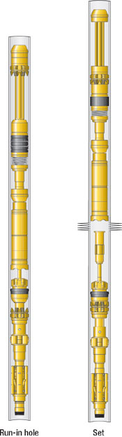 |
Fig. 1. Packer movement cycling.
|
|
STANDARD RUNNING SEQUENCE
Experience thus far indicates the flowing described running sequence for the CTFS. A circulation rate of 1D2 to 1 bbl/min should be established as initial deployment of the system begins. This low circulation rate will assist in creating positive pressure on the coil and serve as a debris barrier to help protect the system while in motion. Once the system gets near the targeted zone of isolation, depth location can be verified with the mechanical collar locator. The depth indicator can then be correlated with existing casing logs for improved isolation accuracy.
The system should be positioned above the setting depth of the bridge plug and the packer indexed with longitudinal movement of the coil. Cycling the packer into the set position at this point will ensure the ability to pull away from the bridge plug once it is hydraulically set. Once the bridge plug is lowered to setting depth, a circulation rate of 1-1/2 to 3 bbl/min (depending on coil size) should be maintained. While pumping, the CT will be lowered onto the bridge plug until a weight loss is noted on the weight indicator (preferred indication is usually 3,000 to 5,000 lbs of set-down weight). While continuing to pump, the packer can then be picked up and a pressure drop noted at surface. Once this occurs, the pumps can be shut down and the packer raised until the desired setting depth of the upper seal in the isolation is reached. The packer is then cycled through longitudinal movement into the set position, Fig. 1, and packed off with recommended tension force related to the size of the packer.
The treatment is then performed, Fig. 2. After it is complete, tension is released to unset the packer and the coil is lowered to retrieve the bridge plug. Excess frac sand is washed up the coil from the top of the bridge plug, and the hydraulic release tool is re-attached to the bridge plug through minimal set-down force. After the bridge plug is re-attached to the system, upward movement of the coiled tubing unsets and equalizes the bridge plug. The system can now be positioned for its next treatment in the well or pulled out of the hole.
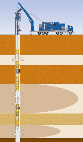 |
Fig. 2. A CT workover rig runs the work string and downhole assembly during the treatment process.
|
|
FIELD EXPERIENCE
Initial runs for the FASTFrac system were conducted in gas wells in Carthage field in East Texas. A typical wellbore for this field consists of either 41D2-in. or 51D2-in. dia. production casing. The casing typically has a good primary cement bond isolating production zones and can often handle internal pressures up to 10,000 psi.
The Carthage wells were initially drilled to between 13,000 ft and 14,000 ft for gas production of the Cotton Valley Sandstone formation, which offered better commercial production rates than the upper Travis Peak formations. Small intervals of shallow gas were bypassed due to the associated completion cost or risk of formation damage to the more prominent Cotton Valley intervals already stimulated by conventional staged fracturing methods.
Most of the bypassed shallow gas zones are located in the Travis Peak formation in depths ranging from 6,000 ft to 10,000 ft. Gas-water contacts within this formation have been observed in a number of fields throughout eastern Texas and northern Louisiana, which indicates that these intervals consist of conventional gas accumulation instead of limited pockets of gas. However, all hydrocarbon-water contacts are located in the upper 500 ft of the formation. The majority of gas production comes from the upper 300 ft of the sandstone-rich formation, with production intervals ranging from 5-ft to 25-ft thick.
After production rates from the Cotton Valley intervals drop, re-entry operations proceed to complete production intervals within the Travis Peak formation, commonly using a rig-assisted plug and packer system conveyed on threaded pipe. Each zone is isolated, broken down and treated separately. A workover rig is mobilized to run the work string and downhole assembly. Stimulation equipment is mobilized to treat the production zone, then demobilized and the zone flow tested for 3 – 5 days. The packer is then released and kill-weight fluid circulated to establish well control. The rig-assisted plug and packer assembly is relocated to repeat this operation.
When this Carthage field well was initially drilled in 1991, the production zones of 6,458 – 6,564 ft, 6,640 – 6,646 ft, 6,768 – 6,774 ft and 6,907 – 6,911 ft were perforated in the Travis Peak formation. Flow tests indicated that the most viable zone was the 6,640 ft – 6,646 ft interval (Interval 2). This zone was then stimulated. Initial production rate of 900 Mcfd caused the operator to decide not to risk formation damage from placing kill-weight fluid to permit treatment of the other production zones.
R. Lacy Services Limited worked with Baker Oil Tools in this pilot project to stimulate the remaining zones with the CTFS. The system was deployed through a standard-length lubricator on 2-in. coil and set in 51D2-in., 17-ppf casing. The system initially provided a 117-ft isolated interval around the first of two zones (Interval 3) to be treated. Once the stimulation was complete, the lower seal of the system was retrieved and repositioned to provide a 70-ft isolated interval across the final zone (Interval 1) to be treated.
About 40,000 lb/zone of proppant was pumped in a 6.9-ppg nitrogen foam slurry. A maximum treating pressure of 4,800 psi was measured at surface. A surface slurry rate of 5 bbl/min was pumped comprising 4 – 5 lbs/gal sand concentration in N2 foam slurry (3,200 – 3,900 scf).
There was an original production expectation of 400 Mcfd based on historical data specific to the field. It was nearly tripled to 1,100 Mcfd on this job, with 10 fewer days spent on fractures and flow testing compared to previous fracture methods. It is believed that this increased production is attributable to the elimination of kill-weight fluid contacting the production intervals. 
THE AUTHOR
|
| |
Ben Holmes is a business development manager with Baker Oil Tools. Based in Houston, he is responsible for new product commercialization in Workover Systems. Holmes was previously an applications advisor responsible for field applications and strategic marketing issues for the Remedial Systems product line. Holmes, who joined Baker Hughes in 1995, has more than 11 years of experience in the oil industry. He holds a BA degree in business analysis from Texas A&M and an MBA from the University of Houston.
|
|
| |
|
|

