|
|
|

By Petroleum Technology Transfer Council |
Microseismic imaging of fracture treatment provides answers, stimulates questions
Microseismic fracture imaging was performed during three hydraulic fracturing treatments in shallow Pennsylvania completions. Results confirmed some common beliefs about fracturing treatments, but they also posed more questions that must be answered by additional testing of the imaging.
Roger Willis, Universal Well Services, Meadville, Pennsylvania; Len Paugh, Great Lakes Energy Partners, Yatesboro, Pennsylvania; and Larry Griffin, Pinnacle Technologies, Inc., Houston
Great Lakes Energy Partners (Great Lakes) employed microseismic fracture imaging, which is only rarely done in the Appalachian region, during three hydraulic fracturing treatments in shallow Devonian-age completions in Linden Hall field in western Pennsylvania. The number of stages varied from well to well, as the “stacked” sands are discontinuous and not always of sufficient thickness or reservoir quality to warrant completion.
Typically, four to six stages are treated in the area. Multiple, overlapping fractures were mapped. Imaging indicated that vertical penetration of fractures into sand bodies, both above and below, was greater than would be anticipated with accepted knowledge. Early results from post-treatment production logging indicate that the adjacent stage fractures did not connect, even though the microseismic images indicated some degree of overlap in nearby horizons. More evaluation is needed to refine the interpretation of how created fracture geometry relates to production performance. At present, there are no immediate changes being made to the stimulation design, pending a healthy debate of the implications of the imaging results.
HYDRAULIC FRACTURE STIMULATION IN THE APPALACHIAN BASIN
Thousands of wells are hydraulically fractured in the Appalachian basin each year, with little clear understanding of what the resulting fractures actually look like. A number of variables exist in the subsurface, including natural fractures, permeability variations, in-situ stresses, faults, etc., that can influence the dimensions and orientation of the created fracture.
In the Appalachian basin over the years, some principal assumptions have been accepted that influence hydraulic fracture design for the majority of treatments. Some of these assumptions were controversial at first but have gained general acceptance over time. Other design factors are the result of local conclusions, based on the results of treatments that have been refined through years of modification. Wanting to test experience-based assumptions, Great Lakes chose to apply microseismic imaging to monitor several hydraulic fracturing treatments in offset Devonian-age completions in Linden Hall field.
MICROSEISMIC IMAGING
This technique images the created fracture by monitoring seismic or micro-earthquake events during the treatment from an array of sensors in an offset wellbore, Fig. 1. The microseismic mapping process detects and plots microseisms induced by changes in stress and pressure associated with hydraulic fracturing in 3D space.
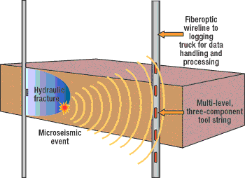 |
Fig. 1. Microseismic imaging plots the created fracture during a treatment by using data collected from an array of sensors in the offset wellbore.
|
|
These slippages occur along pre-existing planes of weakness (e.g., natural fractures) that emit seismic energy that can be detected at nearby seismic receivers. These microseismic data can be assembled to portray the geometry of the created fracture, revealing facets of the fracture including azimuth, height and symmetry. Of particular importance is its ability to define the complex nature of fracture growth as it intersects natural fractures, differing stress zones, etc., in the subsurface.
MICROSEISMIC FRACTURE IMAGING IN THE LINDEN HALL FIELD
The most common stimulation style for the deeper reservoirs of the Upper Devonian is referred to as “ball and baffle.” The well is cased, cemented and perforated using jet perforators. A unique component is the use of multiple, sequentially smaller restrictions called baffles, placed in the casing as it is being run. This technique allows for isolating zones during the treatment by dropping progressively larger frac balls, which land on the strategically placed baffles. Perforating between stages allows complete isolation of each stage.
Separation between sand bodies can be as low as 100 ft, so it is vital to determine fracture height. The fracture could be growing vertically through several target zones from a single stage. In this case, it is necessary to decide if one stage can serve to stimulate several zones in a more cost-effective manner than pumping multiple stages.
FIELD IMPLEMENTATION
Many potential field sites were reviewed. The best candidate to image was in a previously undrilled area that had sufficient area to allow the drilling of several offset wells. This group of wells was cased and set aside for the project, which gave the imaging team the flexibility to pick a centrally located well in which to place the imaging tools.
The distance between wells was on the order of 1,000 ft. Since no imaging had been done before, there was a desire to have the wells as close to each other as possible to maximize imaging quality. The actual operational imaging components did not present significant complications.
A multi-level geophone array was located in Linden Hall 2 and was used to map treatments in Linden Hall wells 1, 3 and 4, Fig. 2. These wells were stimulated with typical Upper Devonian techniques, using frac balls and baffles for isolation, with wells having from three to five discrete stages.
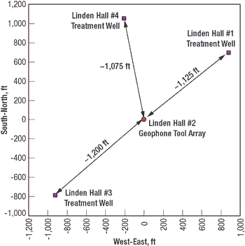 |
Fig. 2. Seated in Linden Hall 2, a multi-geophone array mapped treatments in three nearby wells.
|
|
Figure 3 shows microseismic results for all stages for these three wells. A total of 12 stages was mapped. Average fracture azimuth was N50oE, and fracture half-lengths ranged from 200 ft to 900 ft. Figure 4 is a side view showing results for Linden 3. There was height growth, both upward and downward, out of zone in most stages. Stages three, four and five show significant overlap. Fracture heights ranged from 300 ft to 480 ft in this well. Similar height growth was seen in the other wells.
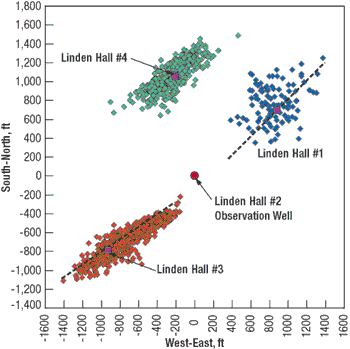 |
Fig. 3. Microseismic results for all stages in Linden Hall wells 1, 3 and 4.
|
|
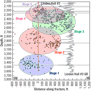 |
Fig. 4. A side view of imaging results for Linden Hall 3.
|
|
Preliminary conclusions from the microseismic fracture imaging results are:
- Fractures do not grow in easily predictable geometries.
- Vertical penetration of fractures into sand bodies, both above and below, was greater than previously thought. Decisions about how many stages to add or delete will be necessary after reviewing the production logging and testing to see if there is communication between overlapping fracture envelopes.
- Calibrated computer models closely resemble the created geometry, as illustrated by microseismic mapping. Matching pressures during the treatment allows the calibrating of subsequent models, which then can be compared with following imaging tests on other wells in the field.
- Fractures appear to be asymmetric in many cases, which could depend on rock properties that need to be evaluated; i.e., do the fractures propagate preferentially into rocks with lower permeability, due to leakoff or other factors that might have an impact on reservoir drainage?
- Fracture azimuth was reasonably consistent in offset wells.
After each well was brought online and cleaned up, production logs were run in an effort to correlate the fracture geometry with each zone’s contribution. Early results indicate that the fractures did not connect, even though the microseismic images indicated some degree of overlap in nearby horizons. This could be due to fractures that did not intersect but instead ran parallel to each other. More evaluation will be necessary to refine the interpretation of how the created fracture geometry relates to production.
The question about the fractures connecting is significant, because there are numerous implications:
- Fractures do communicate with each other. It is not necessary to perform as many stages to drain sand bodies that can be stimulated in one stage.
- Fractures do not communicate but are parallel and non-connected. In this case, it is unlikely that this is an efficient, cost-effective method of draining adjacent reservoirs. One stage might be sufficient to effectively drain targets in this case.
- Sand placement might be less than optimal, based on design goals for fracture conductivity.
- Fractures do communicate, but have a positive impact on production as they serve to better distribute the sand pack, and assure fracture conductivity for each zone in a suitable range.
- Stress shadowing, a term used to describe the effect an existing fracture can impose on a nearby propagating fracture, might have a positive influence on containing the propagating hydraulic fracture.
- Stress shadowing may also be responsible for causing asymmetrical fracture growth.
ECONOMIC CONSIDERATIONS
As this was possibly the first microseismic imaging done in the region, costs were substantially above what they would have been, if the process was in regular use in this area. Additional imaging is being done as a result of the data that were developed in this test. As additional imaging results become available, a better picture of the relationship between fracture geometry and ultimate production will develop. All of this will ultimately help in designing more effective fracture treatments for the many other development wells that will follow. 
ACKNOWLEDGEMENT
The project was funded in part by the DOE and industry-supported Stripper Well Consortium. Partners in this project were Great Lakes Energy Partners, Universal Well Services, Inc. and Pinnacle Technologies, Inc.
THE AUTHORS
|
 |
Roger Willis is senior vice president at Universal Well Services, Inc. He is responsible for managing the firm’s districts throughout the US. He has 26 years of experience in drilling, completions and production. Mr. Willis has a BS degree in geology from Allegheny College. Email: rwillis@univwell.com
|
|
 |
Len Paugh is operations manager, Pennsylvania and West Virginia, for Great Lakes Energy Partners (wholly owned by Range Resources). He is responsible for all aspects of Great Lakes’ operations in the area. He graduated from West Virginia University with a petroleum engineering degree. Email: lpaugh@gl-energy.com
|
|
 |
Larry Griffin, Pinnacle Technologies’ vice president of Diagnostic Services, manages a team responsible for fracture mapping and reservoir monitoring services. Larry graduated from Texas Tech University with a BS degree in petroleum engineering. Email: larry.griffin@pinntech.com
|
| |
|
|

