Production Technology
Water shutoff chemical restores production
A spectacular well had to be taken offline as water breakthrough had overwhelmed facilities. Here’s how the problem was fixed in this North Sea well.
Dave Watson, Centrica Resources, Ltd; Paul McGinn, Halliburton
Centrica Resources, Ltd, has extended the productive life of a subsea production well in Rose field in the southern North Sea, using a rigid-setting fluid as a zonal isolation material to alleviate excessive water production. This water-management treatment helped bring the well back onstream after it had been shut-in due to excessive water production.
Initial gas production from the well was 120 MMcfd before water production began. After treatment, the well returned to its prior glory, but was recently choked back to 70 MMcfd, with a water-to-gas ratio (WGR) of less than 2 bbl/MMcf. Rose field is produced from a single subsea well that crosses two faults, with the trajectory of the well dipping at the end of the horizontal section.
The well, 47/51b-6w, is located about 54 km northeast of Humberside, UK. After only 2.3 Bcf of production, the well was shut-in because water production rates exceeded the capacity of the terminal. The increase in salinity indicated that the water was coming somewhere near the producing formation. Because the formation was unconsolidated, the well was originally completed with pre-packed, wire-wrapped screens in openhole, so simply setting a plug to isolate the water was not feasible.1
A COST-EFFECTIVE SOLUTION
Three solutions were identified to address the water-cut problem:
- Temporarily suspending the well using mechanical or chemical plugs until a viable technique was developed to allow production. This would, of course, result in lost revenue for an unknown period.
- Sidetracking the present wellbore and tapping the reservoir by an alternate route presented substantial re-drilling costs.
- Performing a remedial intervention using a chemical water shutoff treatment would help prevent the water influx while allowing continued gas production. This alternative presented the best economic and technical risk.
The intervention was designed for a jackup environment, located over a subsea well. This included coiled tubing (CT) and fluid pumping operations. The water-producing interval was in a horizontal completion. The basic idea was to seal off this interval, as well as isolate the unsupported annulus between the water-bearing and gas-producing intervals. This challenge required placement of a suitable Zonal Isolation Material (ZIM) that would set quickly without slumping, and set mechanical barriers, all while leaving the upper portion of the well undamaged.
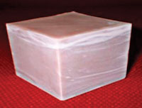 |
Fig. 1. ZIM in solid state, illustrating rigid-setting properties.
|
|
Zonal isolation material. The key component (Fig. 1) in the successful water shutoff was the application of the selected ZIM – a Rigid-Setting Fluid (RSF) with a predictable and controllable right-angle set. (The term “right-angle set” is based on the extreme 90° turn shown on a graph of viscosity vs. time.) This right-angle set is possible because of the fluid’s capability to remain at a low viscosity during fluid placement. It then sets rapidly for a given formation temperature.
The setting process is an exothermic reaction; therefore, the setting time is exponentially accelerated, giving a very short liquid-to-solid transition time. Because of the rapid transition between the fluid state and the solid state, gas migration is anticipated to be zero. As it sets, the material rapidly develops a high-compressive strength; for example, it can reach 3,000 psi within two hours. The material also has zero shrinkage, yet can be removed by drilling, milling or acid. It can also tolerate up to 50% fluid contamination with only a slight reduction in compressive strength development.
The ZIM was engineered to function in a combination of a displacement time of 35 min. and a temperature-related-delay setting time of 8 min. at the bottomhole temperature of 200°F. Because the displacement time begins only when the temperature begins to increase, the treatment can be mixed ahead of time on surface.
Equipment used.
A 95k injector was used, along with the following equipment:
- Tapered coiled tubing of 1-3/4-in. OD, 100-kpsi yield strength, with backup string
- Tubing guide arch with a 100-in. radius
- 4.06-in. side door with a 5.12-in. radial stripper combination
- 4.06-in. triple-combination BOP configured with a shear/ seal, a slip and a pipe ram
- A riser quick-connection sub to minimize the time spent pressure-testing the surface riser connections
- Subsea lubricator cutting valve to eliminate the need for an additional BOP, with a blind/ shear configuration
- Data acquisition system to monitor and record string depths, running speeds, weights, well pressure, tubing pressure, pump rates and pump volumes
- One V8 well-services fluid pump
- A twin compartment, 25-bbl blender.
Implementation process. To begin the operation, the jackup was moved into position. A 7-in., flexible subsea riser was connected to the wellhead via an ROV.
Next, a drift cleanup run was performed with a regular, centralized bullnose jetting nozzle to help ensure that the CT could be run to the target of 13,600-ft MD. Initial software simulations had indicated that, if too much gas was present, it might interfere with reaching this depth, which was essential for required Memory Production Logging Tool (MPLT) runs. With the well shut-in, the CT reached a 13,600-ft MD.
The MPLT runs were performed under both flowing and non-flowing conditions, to determine where the water influx was being produced. After the water-producing region was identified in the toe of the well, a tubing punch, with 11 ft of perforating guns and a pressure-activated firing head, was used to access the annulus between the 4.5-in. tubing and openhole section at 12,650 ft.
The watered-out lower completion was isolated by setting an inflatable bridge plug at 12,750 ft, Fig. 2. The bridge plug acted as a base for the ZIM treatment in a later step of the process and sealed off the lower part of the wellbore.
A retrievable packer was then set at 12,050-ft MD on CT, Fig. 3. The CT bottomhole assembly comprised a motor-head assembly, weight stem, centralizers and a squeeze packer. After the packer was set, an injection test was performed while the CT was still attached to the packer, to determine what flowrates could be achieved through the tubing perforations, as well as the required surface pump pressures. After determining these rates and pressures, the ZIM was pumped through perforations in the 4.5-in. tubing at 12,650 ft into the unsupported annulus, Fig. 4. In the horizontal well section, the ZIM was sandwiched between highly viscous gel pills to help prevent slumping of the ZIM plug.
ZIM placement details. With the CT still stabbed into the squeeze packer, the treatment was placed using 2 bbl of viscous-gel lead spacer, 15 bbl of ZIM and 5 bbl of crosslinked-gel tail spacer. The treatment was pumped into the annulus at a rate of 0.75 bbl/min. with a pump pressure of 4,500 psi until the treatment was over the tubing guide arch, and pumped at 2,000 psi thereafter.
The ZIM set within 43 min., at which point the squeeze packer was unset and the CT was moved to above 10,000 ft, while 5 bbl of water was circulated through the CT to ensure it was clean and free of the treatment chemicals.
The ZIM generated sufficient compressive strength within five hours, and the well was flowed for testing. Another MPLT run was performed to determine whether the ZIM treatment had been successful in preventing water production from the well, Fig. 5. Flow rates equivalent to 40, 60 and 80 MMcfd gas were established.
 |
 |
 |
 |
Fig. 2. Setting bridge plug to isolate the lower well.
|
|
Fig. 3. Setting the packer.
|
|
Fig. 4. Placing ZIM to create a seal between the tubing and liner.
|
|
Fig. 5. PLT logging run shows that water influx has ceased.
|
|
Results. The CT intervention operations were completed in 372 hours, about seven hours of which were non-productive time, including time spent waiting for acceptable weather conditions. Before intervention, MPLT logs showed water holdup from 12,900-ft MD – the region just above the perforated interval at the toe of the well – to 10,900 ft – the region just below the perforated interval at the heel of the well. This indicated that water was being produced from the toe section. This same log shows that the only water holdup in the well is at the heel section, but this was only a mist and could be considered extremely small. Post-operation checks show no flow coming from the original toe section after intervention.
Water-to-gas ratio (WGR) of less than 2 bbl/MMcf was achieved after the intervention had been completed. The WGR has steadily decreased since the intervention took place and is now considerably lower than 2 bbl/MMcf. There has also been a steady reduction in chloride ions found in produced water from the well. This decrease in salinity levels indicates that the produced water is the seawater lost during the intervention, not reservoir water. The intervention proved the chosen solution and the Rose well is currently producing in excess of the forecast post-recovery rate. 
LITERATURE CITED
1 Tudball, I., McGinn, P., Watson, D., “Successful coiled tubing water shutoff solution for a horizontal sand screen completion using novel fluids,” Paper SPE94175, presented at the SPE/ICoTA Coiled Tubing Conference and Exhibition, The Woodlands, Texas, US, April 12 – 13, 2005.
THE AUTHORS
|
 |
Dave Watson is reservoir development manager for Centrica plc, where he is responsible for reservoir management and development of Morecambe Bay gas reservoirs in the Irish Sea, and for Centrica’s assets in the southern UKCS. Watson has 24 years of upstream experience in the Middle East and Australia, and with UK-based companies. He earned BSc and MSc degrees in physics from the University of Newcastle Upon Tyne, and an MSc in petroleum engineering from Imperial College, London. He is a member of SPE and the Energy Institute.
|
|
 |
Paul McGinn is conformance project manager for Halliburton’s Production Enhancement (PE) product service line. He is based in Aberdeen, Scotland, where he is responsible for technical and field support for PE and conformance activities, and for development and commercialization of new technologies. McGinn has 22 years of international experience in most of Halliburton’s oilfield service offerings. He earned a BS degree in manufacturing engineering from Napier University in Edinburgh, Scotland, in 1983. He is a member of SPE.
|
| |
|
|

