Production Technology
New production solutions using deepwater sea floor pumping
Petrobras’ long-term research pays off with two subsea production options.
Perry A. Fischer, Editor
Developing deepwater fields is one of the most challenging issues, especially when marginally profitable. When the complication of multiphase flow is added, two options quickly emerge: seafloor separation combined with an ESP, and multiphase subsea pumping. In offshore areas with substantial infrastructure, viable scenarios for using these two technologies multiply.
BACKGROUND
Each of the various subsea separation and pumping schemes creates a tradeoff between Capex, Opex and revenues. Clearly, the value of increased recovery must be weighed against the added time and cost of subsea infrastructure. Adding to the complexity of this decision is the extent to which the gas/ liquid separation occurs, as it lies on a continuum, up to the point where the gas is too wet to allow continuous flow and/or the liquid phase pump cannot handle the gas cut. Thus, a simple liquid knock-out could be installed on the sea floor, provided that each side (gas and liquid) could handle the inefficient separation, especially for likely future increases in the liquid cut. While subsea separation improves pumping efficiency, the downside is the cost of another riser, long-offset flowline or similar delivery pipe for the gas side.
Gravity separation is a proven technology topsides. Due to the success of a subsea gravity separator in the relatively shallow 1,100-ft waters of Troll field in the North Sea, this should be considered a proven subsea option. In deeper waters, high pressure calls for heavy, thick separator walls. Although smaller diameters will give thinner walls, to compensate, one could increase the separator efficiency (i.e., reduce retention time). Also, an electrostatic field can be applied to the oil and water mixture, using electrostatic coalescence and di-electrophoresis effects to accelerate droplet growth and separation.2 Thus, gravity separators remain good candidates for much deeper water applications. A vertical cyclonic separator is another option.
VASPS
Vertical Annular Separation and Pumping System comprises a cyclonic, centrifugal-force subsea separator combined with an ESP. Three concentric casings are arranged as shown in Fig. 1, with an ESP in the innermost 4-in. string. The entire apparatus is installed in the seabed, with control via an umbilical from the surface. After some serious growing pains, including a blind shut-in of the ESP, leading to its failure, the gas-liquid separator/ ESP unit has been in operation since January 2004.1,3
 |
Fig. 1. VASPS comprises three concentric casings, the intermediate on is slotted with a helix. The innermost is 4-in. tubing with an ESP housing.
|
|
VASPS began in 1990 as an idea. It is part of Petrobras’ Procap 2000, a long-term research program to develop solutions to production and other deepwater problems, which has now been superseded by Procap 3000.
History. In 1991, VASPS research began in earnest with laboratory tests on scaled-down models. By 1993, a JIP was formed with ENI-Agip, Mobil North Sea, British Petroleum and Petrobras. A 14-m high model was built and tested with live well fluids at the ENI-Agip Trecate Test Site, for multiphase R&D, and received some funds from Europe’s THERMIE program.
By 1995, the JIP was recast, with the same players and THERMIE funding, but without the participation of BP. Further R&D continued, focusing on separation efficiency with high viscous oils, pumping system and performance testing of a microwave level sensor, and associated control systems. Testing was moved to Brazil at Petrobras’ purpose-built NUEx facility in Atalaia.
The JIP was again recast in 1997, now sponsored by ENI-Agip, ExxonMobil and Petrobras, with continued support from THERMIE. A VASPS unit was installed in Marimba Field, Campos basin, in October 2000. Due to problems with the host platform, start-up began about a year later.
Field experience. The VASPS unit was installed on well 7-MA-1D-RJS in Marimba field, which is an existing gas-lift satellite equipped with a wet christmas tree. It produces to the P-8 semi-submersible platform, where production from 14 other gas-lifted wells converges. The P-8 can process 50,000 bopd and 1.2x10⁶ Nm3/d of gas. Installation was carried out in 7 days, including drilling the dummy well. Table 1 shows the main data considered for the design of the deployed subsea VASPS unit.
Well 7-MA-1D-RJS is located in 435 m (1,428 ft) water depth and was disconnected from the existing 6-in. flowline and reconnected to the VASPS unit, located in 395 m water depth, some 550 m downstream of the wet tree. From VASPS to the P-8 semi-submersible, a new 6-in. flowline for gas transport to the platform. The existing 6-in. flowline was used to carry the oil. These flow lines have a length around of 1,050 m, while their respective flexible risers’ length is around 660 m. The P-8 platform is located at 423 m water depth.
The unit began operation in August 2001. For startup, the VASPS separator was filled with liquid and then gas was back flowed to ensure that the ultimate liquid level would be around 40% of total height. VASPS initial oil flowrate was 720 m3/d at an ESP variable frequency drive (VFD) of 50 Hz and discharge pressure of 64 kgf/cm2. Oil production was raised to 830 m3/d without using any lift gas. Gas pressure at P-8 was 6 kgf/cm2. The operation continued for four months, until a platform problem required the unit to shut down. This was followed by a restart of the pump into an accidental blind shutoff, leading to motor burnout.1
A workover of the ESP took place in January 2004. By May, the previous oil flowrate of 830 m3/d was re-established, without lift gas. In December 2004, an electrical failure occurred in a subsea electrical jumper that connects the Flow Base to the Head Assembly. The failed jumper was replaced and the system restarted up in January 2005, but now combined with gas lift at a rate as 2,200 m3/d. The new oil flowrate was 970 m3/d (total liquid flowrate of 1,100 m3/d; BSW was 12%). The ESP was last reported pulling 40 amps at 1,990 volts. The VASPS system is still working satisfactorily.
MULTIPHASE PUMPING
In general, the main purpose for subsea multiphase flow pumping is to transfer the untreated production – oil, gas, water and, eventually, solids – from sea floor wellheads or manifolds to production facilities, including FPUs, located in shallower waters, perhaps at great distances.
Potential benefits. Multiphase pumping cannot, by itself, be considered a highly efficient process, but efficiency is far from the only consideration. Capital costs, operating costs and revenue do not necessarily go in lockstep with higher pump efficiency. For example, what if the cost of the pump and the energy to operate it eliminates the building of another platform or Floating Production Unit (FPU), perhaps making viable an otherwise uneconomic field? This might involve using a long-offset flowline or an existing pipeline, pumped to existing facilities.
Even if the wellstream gas/ oil ratio is relatively high – which, by definition, lowers the pumping efficiency – can the waste heat that would necessarily be generated from the multiphase pumping process be captured and used for flow assurance? Would the multiphase pump lessen the effects of slug flow, should it occur? To the extent that multiphase pumping is an added energy source, combining it with natural well pressure might allow production otherwise not possible, and/or faster flowrates and consequently higher revenues; if so, there will likely be an impact on cash flow and net present value. Ancillary benefits and effects – beyond efficiency – must be considered. In any case, multiphase pumping is at least as efficient as gas lift. What is most important is the reliability/ robustness of the pump across a wide range of conditions.
In general, multiphase pumping should increase the reservoir recovery factor by extending the producing life of mature fields. It does this by lowering the effective flowing pressure at which the well would otherwise be abandoned. In deepwater, it’s this head of water that usually kills the well earlier than an equivalent land-based well.
Multiphase pumping can, in certain cases of production from more than one source, allow positive choking to achieve stable co-mingled production from several sources. In other words, boosting the weaker well in order to live with the strong one(s).1 There may be some cases where the same principle could be applied to co-mingled production from several zones within the same well. It can also aid regulatory compliance by reducing flaring.
Subsea multiphase pumping systems can provide novel solutions to production problems when combined with specialized platforms, such as well control, power generation and fluid pre-processing platforms. These, in principle, would be more effective and cost attractive than conventional and autonomous production units.
In some ways, multiphase pumping complicates decision making, owing to the many ways they can be used in providing solutions, but they should be considered tools that bring extra degrees of freedom to petroleum exploitation schemes, particularly in deepwater scenarios.
Development history. Development of a multiphase boosting pump began in earnest at Petrobras and in cooperation with universities and equipment manufacturing companies in the early 1990s. In addition, the Atalaia (NUEx) test site, mentioned above, was built. In 1993, Petrobras entered into a Technological Cooperation Agreement with Bornemann Pumpen A.G. for developing Bornemann’s twin-screw pump concept. Based on the results and on earlier experiences, the two companies agreed that multiphase pumping, based on twin-screw pumps, was reliable enough for onshore and offshore topside applications.
Work proceeded on two fronts: the complete development, including two years of subsea testing for the twin-screw pump, and, exploiting opportunities in offshore topside applications for multiphase pumping. In 1996-‘97 Petrobras conducted a feasibility study to explore development of a complete subsea multiphase pumping system. The study was done in cooperation with Westinghouse (now Curtiss-Wright), EMD (USA) – a traditional manufacturer of electrical equipment, and Leistritz A.G. – a traditional manufacturer of screw-type pumps. Based on the results the study, an SBMS-500 seabed prototype would be developed. In parallel, Petrobras developed topside applications for multiphase pumping.
In March 1997, based on Petrobras’ technical specifications, a Technological Cooperation Agreement was signed with Westinghouse – EMD, which carried Leistritz A.G. as Associated Partner. EMD would supply the motor and integrate the variable frequency drive (VFD), electrical motor and multiphase pump, while Leistritz would supply the pump. Other technical agreements were formed to develop supporting systems, such as power and optical umbilicals, wet-mate power connector, wet-mate optical connector, subsea sensors, compliant subsea modules, heat exchanger and so on. Some of these have resulted in a new components now being used worldwide.
Experience with multiphase pumping. For more than a decade, Petrobras has been developing a subsea multiphase pumping system, called SBMS-500. Research and development costs exceed $65 million. Petrobras is both a user and a marketer of the pump, owing to the fact that its investment and leadership in the project allow it to retain royalties for sales to other companies, as well as to special prices in future acquisitions.4 Curtiss Wright and Leistritz will own the patent for the motor-pump subsystem equipment.
In developing this system, four multiphase pumping systems, based on the same pump type, but with important variations, were previously installed topsides on three Campos basin platforms. These were: Moreia field (P-22 ), Linguado field (P-12 ) and Marlim field (P-18 – nearly operational). In addition to gaining experience with the technology, it allowed cessation of previously compulsorily gas flaring. Papers presented at OTC and Barcelona (reference one and five) report extensively on the technical experience gained with these installations.1,5
The multiphase pump system. The SBMS-500 is a self-priming, positive-displacement twin-screw multiphase pump. This deepwater system is depth rated to 1,000 m and is essentially an adjustable speed, electrically driven twin-screw pump, Fig. 2. It is capable of 500 m3/h (75,000 bpd) flow at a 60-bar pressure differential. A key reason for its selection is the ability to handle gas volumetric fractions (GVF) up to 95% v/v (100% with a 5% liquid re-circulation flow) over a wide range of viscosities. Materials used in the pump can tolerate fluids that are very corrosive and/or abrasive.
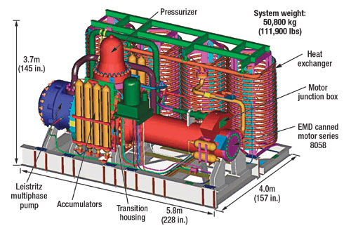 |
Fig. 2. Major components of the SMBS-500 subsea multiphase pump.
|
|
In terms of fluid throughput, this twin screw pump is like a piston pump with an imaginary, infinite length of stroke. Of its two rotors, one acts as a drive, while the other acts as an idler. It’s the rotation/ meshing of the screws that move fluids in any phase. The main technical specifications of the SBMS-500 are shown in Table 2.
There is no contact between the screws or with the surrounding housing. Choices in selecting these clearances affect design criteria. A pump with larger clearances will have a longer operational life, but the tradeoff is a reduction in pumping efficiency. To the extent that the range of fluids, flowrates, viscosities and abrasives can be successfully predicted, the design of clearances, mechanical seals and screw pitch can be optimized for overall performance. A double mechanical seal was chosen for the SBMS-500. An extra margin of performance was gained through a greater frequency/ speed range. Thus, RPM can be increased if there’s an efficiency loss later in the pump’s life due to wear. However, in the case of very high GVFs, the resultant temperature increase and its effect on clearances, as well as loss-of-prime events, are areas of continuing scrutiny and research.
The SBMS-500 onshore development phase was successfully concluded in September 2004, following nearly 1,000 hr of testing. Speeds were varied between 1,400 and 2,000 rpm, at pressures between 30 and 60 bar, including over 700 starts/ stops.
As this is going to press, the SBMS-500 pump is being installed on the seafloor in Marlim field well 7-MRL-10-RJS in 650 m (2,100 ft) of water, Campos basin, Brazil, and being pumped to the P-20 platform. The life span of the SBMS-500 subsea is 20 years under adequate maintenance and operational procedures. It is expected that the multiphase pumping system should almost double production of the MRL-10 well to the P-20 platform. 
ACKNOWLEDGMENT
The author thanks Dr. Elísio Caetano, Petrobras senior consultant and coordinator of the SBMS-500 project, for discussions and assistance in preparing this article.
LITERATURE CITED
1 Caetano, E. F., et al., “Field experience with multiphase boosting systems in Campos basin, Brazil,” Paper OTC 17475, Offshore Technology Conference, May 2 – 5, 2005.
2 Michaelsen, J., “Innovative technology for ultra deepwater gravity-based separators,” OTC 15175, 2003 Offshore Technology Conference, Houston, Texas, May 5 – 8, 2003.
3 Vale, O. R. do, et al., “VASPS installation and operation at Campos basin,” OTC 14003, 2002 Offshore Technology Conference, Houston, Texas, May 6 – 9, 2002.
4 Abrantes, D. , Wertheim, P. H., “Petrobras sets pace for artificial lift and fluid flow research,” Oil and Gas Journal, Vol. 1, 2005.
5 Torres, F. R., Silva A. Jr. and E. F. Caetano, “Petrobras experience on offshore multiphase pumping,” 12th International Conference on Multiphase Technology, BHRG, Barcelona, Spain, May 25 – 27, 2005.
|