Well Logging/ Formation Evaluation
Tubing leak technology saves money for Statoil
A newly developed detection tool allows leaks in wells too small to be found with a PLT, to be discovered and repaired in timely fashion, saving recompletion costs.
Frank Skjerping, Gullfaks Drilling and Well Department, Statoil; and Joel Johns, TecWel AS
In block 34/10 of the northern portion of the Norwegian North Sea lies the main Gullfaks field. The Gullfaks A platform began producing on Dec. 22, 1986, with Gullfaks B following on Feb. 29, 1988, and the C platform on Nov. 4, 1989. Since that time, optimization of production operations and improved economics have been major focus items for Statoil.
The main drainage method at Gullfaks is water injection. Some of the injectors are the only ones injecting fluid into important regions of the field. Shutting in any of these injectors immediately reduces oil production. Injecting water through steel pipe will naturally cause erosion and corrosion, and eventually will cause leaks in the primary well barrier.
Ten years of operational life were expected from carbon steel completions utilized for injection in Gullfaks. As leaks began to occur in these completions, it was determined, upon recompletion, that corrosion and erosion damage was localized. It was obvious that the tubing might have been repaired rather than replaced, and the corresponding well could have remained on injection for several years, saving the recompletion cost. Additionally, lost output, due to cessation of injection operations during workover operations, could have been avoided.
Some of the leaks encountered were too small in rate to be detected by a production logging tool (PLT) or other methods. Locating these leaks early in their development, and having a suitable method of repairing them, would mean considerable cost savings to Statoil. It was decided, therefore, to support development of a tool that could detect these leaks as early, and as accurately, as possible. Parallel development of a hydraulically expanded steel patch was supported, to provide a seal similar to, or better than, the old tubing.
WLD LEAK DETECTION TOOL
Through a joint venture with TecWel AS, Statoil began a project to develop a leak detection tool that can detect and locate small leaks with an accuracy of at least 1 m, and build a service around the tool. For this purpose, a small leak was defined as 0.1 to 20 lpm (0.026 to 5.28 gpm). After several years of development, an e-line-conveyed tool was produced with the ability to accomplish the following:
- Detect and locate oil, gas, water or multiphase leaks
- Detect leaks independent of flow direction
- Find leaks between tubing and annulus
- Detect casing leaks, even while logging from inside the tubing
- Identify leaking gas lift mandrels and other downhole equipment
- Identify wellhead leaks.
The Well Leak Detector (WLD) utilizes ultrasonic sensors in conjunction with a unique method of digital signal processing (DSP). As the tool is passed through the vicinity of a leak, an ultrasonic sensor detects the frequencies generated by the turbulent flow at the leak point. The signal is then amplified and sent through the tool’s DSP module. The DSP unit is equipped with a large amount of flash RAM, running a series of modular signal processing programs. This process filters out any unwanted background energies caused by mechanical noise, or other interference. The result is a fully digitized signal of the leak signature that is then transmitted up-hole via a wireline telemetry system to the surface read-out system. A typical WLD tool string is shown in Fig. 1. A well tractor may be used if required, or the tool may be conveyed on coiled tubing. The WLD can also be run in memory mode.
 |
Fig. 1. Typical WLD tool string.
|
|
CASE HISTORIES
The leak detection tool was first utilized on Gullfaks well 34/10-A-20A. Fig. 2 illustrates a completion typical of Gullfaks field. This well had a leak with a rate ranging from 0.15 to 0.35 lpm (0.039 to 0.092 gpm). It was the project’s objective to locate a leak from the tubing to the A annulus, and to investigate the integrity of the safety valve. During logging operations, the wellhead pressure was 87 bar (1,260 psi). Annular pressure matched the tubing pressure, which, of course, is a positive indication of a failed primary barrier.
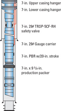 |
Fig. 2. A typical Gullfaks completion.
|
|
To establish an active leak, the A annulus was bled during the logging run. The log from the tool indicated a leak at an expansion joint, at 1,568 m MD RKB. Fig. 3 shows the log produced from the acoustic signature generated by the leak. As long as the leak was active, the signature was repeatable. The leak was confirmed by making an additional pass across a suspected area with the annular and tubing pressures equalized.
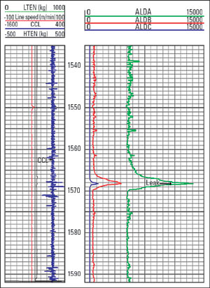 |
Fig. 3. Leak signature, 10 m/min. logging speed, Gullfaks well 34/10-A-20A.
|
|
As shown in Fig. 4, the signature was not present during this moment, thereby confirming the leak’s location. No leak was found at the safety valve, neither by the WLD nor the pressure recordings. Following logging operations, a straddle packer equipped with a polished bore receptacle was installed in the expansion joint, providing a dynamic seal. The well has been operational since its repair, with full tubing integrity.
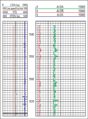 |
Fig. 4. Log absence of leak signature upon equalization of pressure.
|
|
Another case history from Gullfaks field is well 34/10 C-21T2. Analysis of the well’s pressure data indicated a leak rate from the tubing to the annulus of 5.1 lpm (1.34 gpm). During logging operations, the tubing pressure was maintained at 115 bar (1,668 psi), and the annular pressure was bled to assure that the leak was active. A leak signature was located at 590.5 m, MD RKB, in the vicinity of a tubing crossover. The acoustic signature for this leak is shown in Fig. 5. To confirm the leak’s position, it was decided to perform a stationary log.
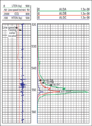 |
Fig. 5. Leak signature, Gullfaks well 34/10 C-21T2.
|
|
The tool was positioned over the suspected leak point, and the annular pressure was manipulated while monitoring the leak signature. The log in Fig. 6, with the y axis being time instead of depth, shows how the acoustic energy generated at the leak rises and falls in direct proportion with the leak rate and the changes in differential pressure between the A-annulus and the tubing. Following logging operations, a straddle packer was also used to seal the leak. The well has operated since its repair, with full tubing integrity.
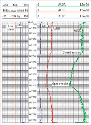 |
Fig. 6. Stationary log – acoustic energy generated at the leak rises and falls in direct proportion with the leak rate and changes in differential pressure between the A-annulus and the tubing.
|
|
Each of the above-referenced scenarios represented a savings of between 15 and 20 million NOK ($2.5 million to $3 million) in production workover costs that would be associated with tubing removal. Additionally, lost production, due to cessation of water injection from the candidate wells, was minimized.
BEST PRACTICES FOR GULLFAKS
To continue injection until permanent repair can be done, leak detection will be performed by the WLD, followed by an MFC (multi-finger caliper), to investigate whether it is worthwhile to repair the tubing. The MFC, in combination with the WLD, provides extremely useful data for evaluating the best way to proceed with the well. For water injection wells, following logging operations and evaluation, an injection valve is temporarily installed below the point of leakage.
At the same time, an official note is sent to the Norwegian Petroleum Directorate, and written acceptance has to be received prior to restarting the injection. The deviation from regulations is normally given for six months. This allows Statoil ample time to plan the operation and fit it into the work program for different platforms.
In addition to cost savings connected to the repairs mentioned above, Statoil has realized considerable savings in actual leak detection operations at Gullfaks. Before joint development of the WLD tool, success in localizing the leaks was often random. As experience has been gained in the use of the tool, operations have been further streamlined by assuring that the leaks were in a dynamic condition prior to logging. Most of the leak detection projects have been completed within a 24-hr period. More often than not, they have been completed in one tool run.
Use of conventional straddle packers for leak repair, although fairly inexpensive, reduces access, due to the loss of inside diameter. Therefore, development of a hydraulic, expandable steel patch will continue. The first version will need to be installed on pipe or coiled tubing. A planned, second version may be installed by wireline tractor.
Statoil will continue to refine operations and techniques to reduce costs. The WLD will remain a valuable diagnostic tool in Statoil’s production operations. Experience at Gullfaks, plus other areas, has confirmed its value as a highly sophisticated, extremely reliable and cost-effective leak detection tool. 
THE AUTHORS
|
 |
Frank Skjerping is a lead well engineer for Statoil’s Gullfaks field. He has worked at the company since 1997, in various engineering and management positions in the Gullfaks Drilling and Well Department. He earned a bachelor’s degree in mechanical engineering from Bergen Engineering College in 1985. franks@statoil.com
|
 |
Joel Johns is the US sales and marketing manager for TecWel AS. He holds a degree in electrical engineering technology from Louisiana Tech University. Mr. Johns has 15 years of experience in manufacturing, design and marketing of oilfield equipment and services. joel.johns@tecwelinc.com
|
| |
|
|

