Oil Country Tubular Goods
Tapered coiled tubing reaches extreme penetrations
Tapered coiled tubing strings not only increase operating well depth ranges by 55%, but they also increase the maximum penetration in horizontal wells by at least the same amount.
Ivor McCourt, Hydrastatic Systems and Jorge Kubie, Napier University Edinburgh
In their recent article, Fowler and Courville described a new coiled tubing (CT) string development that can increase operating well depth ranges by 55%. This article described the new system/ service at length in the February 2005 issue of World Oil (pp.81 – 83). The development is based on tapered outside diameter (OD), which is made possible by joining sections of varying outside diameters, using specially designed transition segments.
The resulting string features a smaller OD and wall thickness on the bottom, and progressively larger OD and wall thickness near the surface. The string’s larger cross-sectional area at the surface supports the greater suspended tubing weight, thus allowing extreme-depth CT intervention. A significant additional benefit is the lowering of the string’s total weight, which is of importance when limited handling capacities and weight restrictions are imposed by operators.
This approach is of course, a good engineering solution to a well known engineering problem of designing a suspended rod or a tube with a variable cross-section, in which tensile stresses are constant. The achievements described by Fowler and Courville are notable in the engineering development of the technology, including the handling equipment and, particularly, the injector.
However, there is one additional, major benefit from this technology that is not considered in the article. This particular arrangement allows a significant increase in the limit on the penetration of coiled tubing in horizontal wells, by delaying the transition to helical buckling and the subsequent lockup. A novel approach to modeling and analyzing this phenomenon was recently developed.2
EXPERIMENTAL WORK
The buckling of tubes in horizontal wells depends on the clearance between the tubing and the well’s inner casing, the tubing’s design, and the substantial frictional forces generated as the CT is pushed into the horizontal well. As the penetration increases, frictional forces increase too, and the tubing buckles. The buckling is initially sinusoidal but eventually transforms into helical.
It should be noted that the term sinusoidal buckling is not accurate, since the shape is not sinusoidal. The term is used in this work because it is widely used in literature for the pre-helical deformations, and because the shape is indeed close to a sinusoidal curve.
At this point, the force required to push the tubing rises dramatically, and the maximum penetration is then rapidly reached. This is demonstrated in Fig. 1, which shows the modeling of CT in a horizontal well, using 14-mm ID and 5-m-long acrylic tubing. The tubing initially enters the well in a straight line.
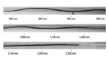 |
Fig. 1. Deformation trends in plan view.
|
|
After a certain length is inserted, the initial straight section starts deforming. The initial deformations appear sinusoidal. With further insertion, the length of the sinusoidal cycles decreases, and the amplitude increases. As the amplitude increases, the deformed tubing begins to move progressively up the walls of the tube. This continues until a situation occurs, when helical deformations suddenly appear. The region with the fully developed helical deformations is relatively small.
A qualitative assessment of the process indicates that, to shorten the lengths required to achieve full locking of the tubular pipe, its flexural rigidity should be as low as possible, and the friction between the tubular pipe and the well should be as high as possible.
Several materials and shapes of tubular pipe were investigated, and rubber formed into small-diameter rods was finally chosen. To allow for visual observation of the behavior of the rods, glass cylinders were chosen to model the well. Acrylic cylinders were also investigated, but these proved unsuitable, because a static electric charge formed on the acrylic cylinders during the insertion process. This resulted in non-repeatable effective increase in friction. The use of glass eliminated these effects.
Experimental tests were carried out using rubber rods with diameters (d) of 2, 3, 4, 5 and 6 mm in constraining glass tubes with internal diameters (D) of 8.6, 13, 15, 19, 22.8, 28.6 and 33.4 mm. This enabled a full examination of the impact of rod stiffness and D/d ratio. All experimental results for the insertion of the rod into the tube demonstrate similar qualitative trends, shown in Fig. 1, which was obtained during the preliminary tests using d = 3 mm and an acrylic tube with D = 14 mm.
The aim of the insertion tests was to establish the load – insertion relationship for a particular diameter of rod and tube. With the range of rod and tube diameters available, this allowed a comprehensive picture to be determined. Experimental results for the insertion tests were translated into graphs of the required insertion force against the inserted length. Each graph showed a large number of experimental runs. Typically, about 10 runs were taken for each D/d configuration. The ambient temperature during these series of experiments was between 13° and 18°C. The results for d = 3 mm are presented for D = 8.6 mm in Fig. 2.
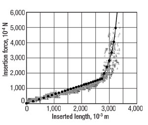 |
Fig. 2. A comparison of the theoretical results for µ = 0:62 (black dots) with the experimental data (grey symbols) for d = 3 mm and D = 8:6 mm.
|
|
ANALYSIS
By simple visual observations of the phenomena involved, it is possible to arrive at a qualitative description of the process. As the rod is inserted into the tube, there is initially an apparently straight section. As the inserted length increases, the rod begins to deflect into sinusoidally shaped wave forms, initially with small amplitudes and long pitch lengths. With further insertion, the amplitude of the waves increases, and the pitch length decreases towards the insertion end.
The observed asymmetric buckling phenomenon occurs because the force that causes buckling arises from the friction between the rod and the tube, and therefore increases as the inserted length increases. The larger force at the insertion end of the tube causes larger lateral amplitude and shorter pitch length.
As the inserted length continues to increase, the rod moves up the inner surface of the tube, eventually above the halfway mark. This causes the rod to be forced upwards to contact the top surface of the tube and helical buckling occurs. When full helical buckling occurs, the insertion force rises dramatically, and only limited further insertion is possible.
Typical experimental results in Fig.2 indicate that during the initial stages of the insertion process, the required insertion force is proportional to the inserted length. Moreover, the retraction force (measured during the rod withdrawal) required is, for a given length of the rod, almost identical with the insertion force required for the same length of the rod. This suggests that the only forces present during sinusoidal buckling are the frictional forces between the rod and the inner surface of the containing cylinder.
Subsequent analysis focused on several stages:
- Initiation of sinusoidal buckling
- Subsequent shapes during the sinusoidal buckling
- Forces present during sinusoidal buckling
- Transition to helical buckling
- Forces present during the helical buckling
- Limits on rod penetration.
It was found that the dimensionless length of the transition to helical buckling is a function of three dimensionless groups:
- The friction coefficient µ,
- The parameter EI/µLgd 3), which combines the relevant material and physical properties of the tubular pipe
- The geometry parameter, D/d.
The dimensionless length of the transition to helical buckling decreases with increasing first parameter and third parameter, and increases with increasing second parameter.
The model developed in the present work can be extrapolated to typical field situations using coiled steel tubing (E=2.1x10¹¹ N/m2 and r=7,900 kg/m3) with outside diameter d=38 mm and wall thickness t=3 mm being inserted into horizontal casing with D=100 mm. The maximum penetrations for µ=0.3, 0.2 and 0.1 are about 1,200 m, 1,800 m and 3,600 m, respectively. This agrees with the field data available.
CONCLUSIONS
The work shows clearly that the CT transition to helical buckling at any section is controlled by: 1) the local clearance between the tubing and the well, and the tubing design at that section, and 2) the cumulative frictional force between the tubing and the well, from the free end to that section.
Using tapered sections, the local conditions remain the same, but the cumulative weight and, thus, the friction are considerably lower. This allows much greater penetration before helical lockup occurs. Analytical results indicate that the improvement in penetrations is at least as good as the increase in operating depths.
Thus, tapered CT strings can significantly increase available reserves by increasing the operating depth and the horizontal reach. 
LITERATURE CITED
1 Fowler, H., and P. Courville, “Tapered coiled tubing reaches extreme depths,” World Oil, February 2005, pp. 81 – 83.
2 McCourt, I., T. Truslove and J. Kubie, “On the penetration of tubulars in horizontal oil wells,” Proceedings IMechE: J Mech Eng. Sci. vol. 218, pp. 1063 – 1082, 2004.
THE AUTHORS
|
 |
Ivor McCourt is engineering director of Hydrastatic Systems Ltd, a company providing services and consultancy to marine and oil industry. His experience is in surface and subsea installations, including design of pipelines and flowlines, subsea hydraulic control systems, risers and tensioners, and coiled tubing systems. He holds a PhD degree from Napier University, Edinburgh.
|
|
 |
Jorge Kubie is a professor of mechanical engineering and head of the School of Engineering at Napier University, Edinburgh. His research interests are mainly in the areas of multi-phase thermal hydraulics, design and safety, and coiled tubing systems. He holds a DSc(Eng) degree from University of London for his work on thermal hydraulics of multiphase systems. He is a co-author of about 80 technical papers.
|
| |
|
|

