Oil Country Tubular Goods
Drillstring telemetry evolves toward full commercialization
Truly real-time, ultra-fast data transmission passes milestones in field tests.
Perry Fischer, Editor; and Katie L. Wigginton, Associate Editor
With premium drilling tubulars converted for telemetry use, high-speed data transmission along the drillstring is now enabling full communication between downhole tools and the surface. For this purpose, in 2000, Grant Prideco and Novatek (a Utah-based engineering company) formed IntelliServ, Inc. With support from the US Department of Energy, the new company has developed telemetry drill pipe (IntelliPipe*) and other telemetry drillstring components. This is an update of our last report on this technology in World Oil 2003. Tool developments and field tests are discussed.
BACKGROUND
Mud-pulse telemetry is the industry standard for data gathering while drilling. It has limitations on data transmission. Its typical low rate of 4 to 12 bits/sec is too slow for high-resolution data gathering and data-intensive activities, such as seismic-at-the drillbit or taking downhole images. Also, mud pulse cannot transmit data during well-control problems, underbalanced drilling with foam, or air/mist drilling.
Other technologies have been created to get around these problems, such as memory logging, electromagnetic transmission and downhole data decimation. Disposable optical fiber is still being considered as a high-speed solution as well, but does not appear to be viable at this time.
Each of these has its drawbacks. Memory logging is not real-time. Electromagnetic transmission has relatively shallow depth limits and is subject to specific geological circumstances. Although the use of downhole antennae can extend this, these can be very problematic.
THE SYSTEM
The system provides bi-directional communication, allowing commands to and from the BHA and other nodes along the drillstring.
Drill pipe and drill collars. Early trials of wired drill pipe attempted to create a hard-wired connection between/ across pipe joints. These inevitably failed due to the inability to have the connection precisely align, connect, and stay insulated (dry).
The present technology has the cable running the length of, and inside, the drill pipe, ending in a ferrite-lined groove at the pin nose, and again in the corresponding box shoulder. The ends of the drill pipe are kept in close proximity to each other but do not require contact, Fig. 1. Transmission occurs by way of induction across the gap between the pin and box ends.
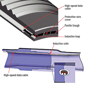 |
Fig. 1. Cutaway of the tool joint showing the cable running alongside the drill pipe. The data cable is surrounded by a ferrite trough.
|
|
The stainless-steel armored cable is held in tension inside the pipe and lies against, but is not attached to, the pipe wall, thus allowing tight-radius bends while drilling, without straining the wire. In extreme cases, the wire could approach the pipe’s centerline, Fig. 2.
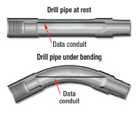 |
Fig. 2. The cable wire is held in tension and in a worst case scenario, can approach the pipe’s centerline when the pipe is subjected to bending.
|
|
A double-shouldered connection maximizes strength at the drill collar, enabling the necessary modifications to the existing premium connection. As for heavyweight drill pipe and collars, these are of similar design as regular intelligent pipe. Modifications for these have been extensively fatigue tested and found worthy of field work.
Repeater joints. Power losses are greater in an induction system, so, to ensure transmission, an amplifier/ signal conditioner/ repeater was created, called the IntelliLink.* These special 3-ft-long subs are threaded onto the bottom of a 28-ft joint. They are placed every several hundred to more than 1,800 ft in the drillstring (still being determined by field tests), and are lithium battery powered, lasting up to 60 days on a battery pack. Vibration, temperature and/or pressure data can be collected at each booster location, if appropriate sensors are installed.
Top drive swivel. The signal passes from the drillstring to a top drive swivel sub. This is a special “floating” swivel ring, allowing signal transfer to a computer system on the surface. Once the signal is in the computer, it can be transmitted anywhere the Internet permits, worldwide.
Drilling jars. While more challenging to design, wired jars have been built with the same, basic induction type of connections. The internal wire, however, was encased in a coiled spring, to withstand jarring effects. The design was subjected to more than 100 firings without any noticeable effects on transmission.
OPERATOR CONCERNS
Operators had concerns that the system might interfere with various through-drillstring operations, such as gyro survey, free point tools and string shot carriers, as well as various pump down devices, wipers, darts, wet-connect wireline, etc. Although actual cable orientation would be random in the field, tests were performed in the worst-case scenario shown in Fig. 2, with a bend equivalent to 12°/100 ft.
For the wiper dart test, two 5-in., 19.5 lb/ft joints of telemetry pipe were used in a bench setup. Since the bend was upward, gravity made the effective dogleg severity equivalent to 16°/100 ft. Pumping at 0.5 bbl/min, various darts and wipers were pumped while monitoring transmission rates. No ill effects were observed.
For the other devices such as wiper balls, string shots, wireline and gyro tools, 30 joints of 5-7/8-in., 23.4 lb/ft telemetry pipe, with an amplifier at the bottom to generate signal, were deployed in a well at the GTI Catoosa test facility. Each tool was run in at normal-to-above-normal speeds four times. No unwanted effects were observed either on the tools or the transmission rates.
FIELD TESTING
In addition to the two field tests discussed in our October 2003 report, full-scale tests commenced in mid-2004.
Third well. A well was drilled to 13,834-ft using 5-in. telemetry pipe, with 11 amplification joints placed about every 600 ft. Intelligent hardware were only used in the first 8,000 ft, which was all vertical hole. Typical data transmission rates were 2 megabits/sec. In addition, temperature and battery voltage data were monitored off of the IntelliLinks.*
Fourth well. A 13,508-ft field test was drilled, using 9,178 ft of 5-in. intelligent drill pipe. Thirteen amplification joints were placed every 600 – 800 ft. Maximum depth was temperature limited. Data transmission again proved to be 2 megabits/sec. Much of the telemetry drillstring went through a kick-off at 2,000 ft. A maximum of 18.7° deviation, and a maximum of 3.87°/100-ft dogleg severity was seen.
Fifth well. With BP as operator, a fifth well was recently completed to a total depth of over 13,000 ft using 5-in. telemetry drill pipe. The job was successful providing real-time data throughout the field trial, including sending information to engineers in Houston and Provo via satellite.
Lessons learned. Results from these wells met all of the intended objectives. However, there were lessons learned. To minimize time spent, the best time to swap out the conventional drill string is between rig moves, when the drillpipe is normally laid down.
It was also shown that the amplification joints have temperature limitations of about 185°F, as expected. When faced with excess temperature, the boosters shut down, but regain use after temperatures are lowered.
The crew needs to be familiar or trained with double-shoulder connections. These required careful application of thread compound and a stabbing guide. The learning curve on this was rapid, with only two connections galled.
The swivel at the top of the drillstring, where the signal is stripped off, was quite an elaborate rig-up of cables and wires, necessary to keep everything secure and as much out of the way as possible. The first rig-up of these wires took 5 hr; subsequent rig-ups have narrowed this to 1.5 hr.
Mis-stabs led to significant damage of the top swivel, eventually resulting in loss of signal due to crushing of the swivel inductive ring. This could have been partly due to the crew’s combined inexperience with both stabbing procedures and the newly installed top drive. After some additional training, a replacement swivel was installed that remained in excellent condition for the remainder of the trial. In addition, interference from high powered surface equipment was severe. This was reduced through grounding efforts, but subsequent surface cabling that was much better shielded and grounded was found to be a solution.
For protection against damage when racking, the drillstring has pin-tip protectors. These did not appear to increase handling time. No damage to pin tips was observed during tripping.
A conventional MWD/LWD was run for a portion of the fourth well simply to validate the high-speed transmission concept. This required the development of an interface by Baker Hughes. All of the primary objectives were met in this test.
SUMMARY
In all, this new technology has been deployed in five test wells as of May 2005. Thus far, over 3,000 hr of operation and more than 40,000 ft of hole have been drilled with intelligent drillstring to test the system, successfully demonstrating the concept. With continuation of land-based field testing and partnering with more clients ongoing, obstacles are expected to be overcome, and commercialization within a year or so is planned.
There are, however, still some bugs to shake out, real-world abuse to prove able to withstand, and a temperature problem that needs improvement.
In a sense, new technology such as this is expensive and, therefore, most appropriate in expensive wells. Expensive wells tend to be deep, and thus, hot, or at least hot enough to be a potential problem for downhole electronics. This is a problem that, like LWD temperature problems, should be solvable for the most part. The next generation of downhole amplifiers should be able to handle 300°F.
The new, wired drillstring telemetry is well along the path to commercialization and should not experience the same limitations of previous high-speed telemetry technologies. Once commerciality is achieved, it will usher in a new era in high speed, high-resolution, truly real-time drilling data. 
ACKNOWLEDGMENT
A significant portion of this article was based on SPE/IADC 92477, presented at SPE/IADC Drilling Conference held in Amsterdam, The Netherlands, 23 – 25 February 2005. *IntelliLink and IntelliPipe are registered trademarks of IntelliServ, Inc.
|

