Well Control and Intervention
Underground blowout causes and symptoms
Although always caused by a pressure differential, there are many ways that flow can be initiated, and signs of a problem may not be obvious.
Neal Adams, Neal Adams Services, Houston
Underground blowouts (UGBOs) are sufficiently predictable that they can usually be found, if you look hard enough. Yet, they often contain an element of unanticipated behavior that can make each one unique. Ignoring the problem, or even the potential for the problem, is never a good decision, but it’s one that is often made. This article describes common manifestations of UGBOs and some of the unusual and often extraordinary behaviors of UGBOs.
OPEN HOLE UGBO
Often, both the problem and the solution are simple. Nonetheless, thousands of wells have been lost due to this most common UGBO scenario, shown in Fig. 1. In this example, the well has a proposed 9,750-ft TD. Surface casing is set and cemented at a moderately shallow vertical depth of 2,500 ft. After drilling out the plugs and cement, a short, 5- to 15-ft section of open hole is drilled and the BOPs are closed.
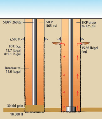 |
Fig. 1. Typical open hole UGBO.
|
|
A formation integrity test is conducted to confirm a good cement job and determine the formation’s resistance to fracture. Perhaps the most common method is the leak-off test (LOT), where pressure is applied until the formation accepts a small amount of drilling fluid. An optional method is the formation integrity test (FIT), which confirms that the formation can resist a pre-determined amount of pressure. The LOT and FIT have specific areas of applicability; discussing these is beyond the scope of this article.
For our example, assume we ran the LOT with a 9.1-lb/gal mud and determined a leak-off value of 470 psi. This pressure is converted to other units of equivalent mud weight, so that we can easily compare it daily to the drilling fluid density in our well. The equivalent formation fracture strength, refr, at the casing seat, in lb/gal is:
| |
 |
(Eq. 1) |
| where: |
pvdcs |
= |
Pressure at vertical depth of casing seat, psi |
|
dvsc |
= |
Vertical surface casing depth, ft |
|
rm |
= |
Density of the mud |
|
0.052 |
= |
Conversion constant, psi/ft/lb/gal |
So, in this case, substituting,
Thus, the formation immediately below the casing seat should be able to resist fracture by any combination of pressures equaling a 12.7-lb/gal equivalent or less.
As a general rule, formation strength increases with well depth. Stated another way, the most shallow, exposed open hole formation should have the lowest fracture resistance. Although this rule holds most of the time, it is often fraught with exceptions, e.g., depleted zones, lithology changes, unsealed fault lines, etc.
In the common open hole UGBO scenario, the well has a long openhole section relative to the depth of the surface casing. Perhaps gas-cutting and tight hole sections were drilled that resulted in a mud weight increase to 11.3 lb/gal. Further, perhaps the well site geologist wanted to drill 250 ft farther than the original plan, which required a mud weight increase to 11.6 lb/gal at 10,000 ft.
Then, a drilling break is observed and a flow check is made. The BOPs are subsequently closed with a 30 bbl pit gain. The shut-in drill pipe pressure (SIDPP) is 260 psi and the shut-in casing pressure (SICP) is 565 psi. The 260-psi drill pipe pressure shows a kick requiring a 0.5 lb/gal mud weight increase to 12.1 lb/gal from 11.6 lb/gal. The SICP is constant at 565 psi for several minutes and suddenly drops to 325 psi, Fig. 1. This represents classic UGBO behavior.
The cause should be obvious. The previously determined formation fracture pressure resistance, refr, of 12.7 lb/gal was exceeded. The SICP of 565 psi allowed the creation of a kick-imposed equivalent mud weight, rek. Using Eq. 1 and substituting, we have:
| where: |
rek |
= |
Equivalent kick mud weight at casing seat, lb/gal |
which is greater than the 12.7 lb/gal equivalent formation fracture pressure resistance.
What happened was, a fracture developed at the casing seat, allowing mud losses and a subsequent reduction in surface casing pressure. The loss of surface and hydrostatic mud pressures created a corresponding reduction in wellbore pressure that fell below formation pressure. Flow continues and the influx volume increases.
In field operations, a delicate balance exists between mud weights to control formation pressure and mud weights that would result in losses to weaker, exposed formations. Common operating margins are 0.3 – 1.0 lb/gal between formation fracture pressure and wellbore equivalent mud weights, re. When you find yourself walking a mud weight tightrope and bouncing between mud gains and losses, there are three possible options from which to choose.
- Cease operations and plug the well.
- Run casing or a liner.
- Continue drilling and wait for the almost certain UGBO.
Some operators will not entertain the first option as worthy of consideration, which often proves to be a mistake. Option 2 appears attractive because it avoids a UGBO. Unfortunately, it necessitates additional considerations. Recall that we had drilled too far ahead in depth without casing and were walking the mud-weight tightrope. Running casing or a liner creates surge pressures that invariably results in lost circulation in this scenario. Further, circulating higher density cements is almost a “sure thing” toward poor-to-nil cement effectiveness.
Option 3 is the one most commonly selected. Options 1 and 2 require that decisions be made and action taken. Option 3 requires no action other than to continue drilling. Don’t despair though, maybe you’ll get lucky and reach TD without an incident. Another name for this game is roulette.
Returning to the casing seat, the flow path is not omnidirectional, i.e., it doesn’t flow in all directions simultaneously, but rather, it follows the path of least pressure resistance. Often, this occurs along bedding plans, which may be horizontal. If so, UGBO flow is perpendicular to the wellbore.
Some field cases demonstrate that the least resistant path may be vertical in a poorly cemented, casing/ open hole annulus. As the flow moves upward, if the kick fluid contains gas, we find that,
at the decreasing depths behind the pipe. The flow may follow the annulus or divert to soft, shallow rocks leading to surface.
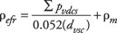
Fig. 2 shows a well drilled offshore Papua New Guinea. A deep kick traversed vertically to the sea floor via a series of poorly cemented casing annuli. The rock above the 6,944-ft reef interval would not sustain a full column of drilling fluid, resulting in a poor cement shoe on the 9-5/8-in. casing. While cementing the 13-3/8-in. pipe, lost circulation to fractures inhibited cement circulation to surface, which was the primary objective.
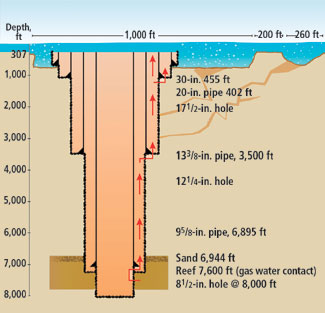 |
Fig. 2. Case history of behind-pipe flow resulting from
poor cement.
|
|
Normal drilling fluid circulation through the lower reef section was impossible, which allowed a reduction in hydrostatic pressure and a subsequent kick influx. Shut-in at the initial kick signs caused surface pressure buildup as gas came up the well, thus forcing mud out the bottom into the reef section. Equivalent circulating densities it the 9-5/8-in. shoe increased, which caused annular flow around the poorly bonded shoe. Likewise, flow continued up the 9-5/8-in. x 12-1/4-in. annulus until encountering the 13-3/8-in. shoe, which proved to be only a momentary diversion.
Formation fluid influx usually continues until bridging formations pack-off the annulus. Wellbore formations become unstable for several reasons. Formation fluids that displace drilling mud are lower in density, which reduces annulus-to-formation differential pressures. The reduction can reach negative values, which promotes formation instability.
Further, formation influx is often not compatible with drilling fluids. Saltwater influxes flocculate freshwater mud filter cakes and accelerate filtrate loss, as well as substantially increasing the cake’s coefficient of friction. Increased filtrate loss also leads to bridging.
Bridging can occur anywhere in the open hole and is a function of lithology, formation integrity, differential pressure, mud type and fluid influx. It is a common mistake to assume the bridge is very shallow or at the hole bottom.
The next common feature of UGBOs is that the drill pipe will usually become stuck. The original cause of sticking is often from bridging or hole pack-off; it can be identified with free-point or stuck-pipe logs. However, the stuck pipe section doesn’t stop here. In time, it usually spreads over the entire open hole section up to the casing seat. The sticking is related in part to the aforementioned filter cake flocculation and its increased friction coefficient. As will be shown later, rarely is it possible to fish the stuck pipe over a long open section. Sidetracks and re-drills are normally required.
MULTIWELL SITES
Wellsites in near proximity can allow damage caused by a single well to adversely affect other wells. This is common on both land and offshore platform sites. It is not uncommon for a single well UGBO to 1) pressurize annuli of adjacent wells, 2) cause pipe damage or severed casing, 3) settling, or 4) result in a surface blowout in one or more wells.
It should be obvious that a worst-case platform event can be devastating and costly. A few documented cases have resulted in complete platform losses. Some have settled and disappeared in mudline craters.
CASED HOLE EVENTS
Fig. 3 depicts cased hole events. Common causes of the casing or tubing breach are improper design, erosion, corrosion, connection leaks or cement failures. Some formations may shift causing the casing or tubing to shear or collapse. The shifting can result from depletion-related subsidence, a UGBO pressuring a formation in a multiwell field and affecting adjacent wells, or the movement of plastic formations such as salt. Cased hole UGBOs often are substantial. The flow source, such as perforations, is likely to remain open through the event. If it’s internal to the pipe, the vertical flow path through tubing and/or casing can have a substantial cross-sectional area. The breach point may be shallow, resulting in a low receiving-zone pressure; that is, the flow pressure, whose source is much deeper in the well, is easily greater than the receiving formation pressure.
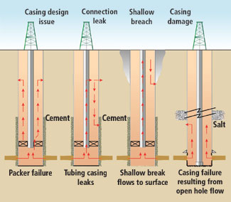 |
Fig. 3. Cased hole UGBO scenarios.
|
|
Since flow is proportional to the pressure differential and flow area, it follows that flowrates can be large. Several documented field cases have been estimated at 40 to 60 MMcfd. Obviously, these rates are substantial. Kill complications can result from difficult working conditions in a wellbore with high flowrates. Snubbing units are often required. Relief wells are occasionally the only feasible control option.
A shallow breach point with accompanying high flowrates can wreak havoc in near-surface formations. Cratering can occur. Also, pressure and fluid charging has been known to occur over an extended area. A few field cases demonstrate charging at distances up to 3,500 ft from the source well. This degree of charging may occur with shallow zones, but is almost non-existent with deeper receiving zones.
Cased-hole UGBOs often evacuate annular packer or completion fluids. If the flow is gas, it migrates up the annulus, while heavier annular fluids, such as brine, are forced down the well and out the exit point. Elevated casing pressures can result from this situation.
An UGBO involving a cased hole requires attention because the situation usually involves a more complicated control effort in terms of specialty equipment, blowout duration and cost. Also, experience indicates frequent events where the receiving zone is relatively shallow. Since the charging pressure is often much greater than the receiving pressure, it can induce a fracture extending to the surface. Cratering under and around a drilling rig can occur, which may result in loss of the rig.
Common options for the communications path in cased hole events are more varied than with open holes. Hopefully, the reader will observe that the multiplicity of flow options necessitates an expansive array of preferred kill techniques.
EXTRAORDINARY UGBOS
These events are often very difficult to prevent as well as control. Consider the common problem of a pressure-depleted zone due to production, with higher-pressure zones lying above. Assume that the zone is a prolific gas producer and has been under active production for decades, even though the current BHP is low. During the early life of the field, operators would drill through the sand, set and cement casing without incident. This procedure is no longer applicable because the sand will not support normal mud weights, much less the higher mud weights required to drill through the overlying higher-pressured zones. Casing must now be set between the high-pressure zone above and the low-pressure sand below. The UGBO can arise because of the pressure difference between these formations, Fig. 4.
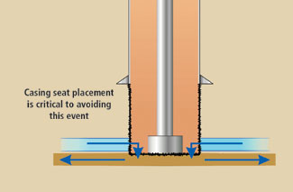 |
Fig. 4. Typical UGBO associated with deep production and depleted zones.
|
|
If the receiving zone is penetrated without casing protection, a prolific UGBO is initiated. After fighting the problem for a few days, you might be asking for divine intervention. Situations similar to this exist in the Hollywood sand in southeast Louisiana, India’s Bombay High field and Mexico’s Cantarell field.
BEHIND-PIPE FLOW
Zones flowing behind pipe are not unique to the oil and gas industry. Usually, flow origination is a simple issue of pressure differentials between the upper and producing zones and/or cement failures.
Many areas in the Middle East must contend with a unique type of behind casing flow. The region contains a shallow zone known as the Umm Er Radhuma or UER. It is a highly fractured, vugular carbonate, which gives it the potential for high flowrates. It is usually located in the shallower well depths, i.e., 1,000 to 3,000 ft, with zone thicknesses of 50 to 300 ft or more, Fig. 5.
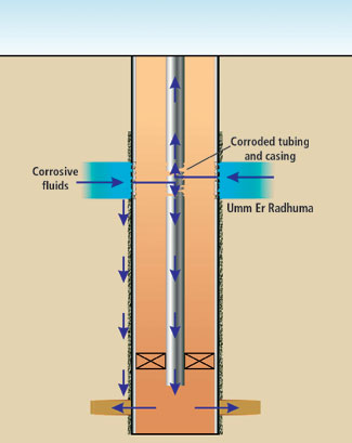 |
Fig. 5. Middle East UER formation UGBO scenarios. Umm Er Radhuma formation contains H2S that can corrode casing and tubing, leading to UGBO.
|
|
In most cases, the intermediate or production casing was not cemented to surface and the UER was left exposed. When attempts are made to cement the zone, success is usually nil-to-poor cement bonding and encirclement on the casing.
The UER has some hydrogen sulfide associated with its water in many areas. The amounts can range from slight traces to rather significant concentrations. Localized areas where the hydrogen sulfide content is high may have originated from producing field wells leaking sour oil or gas into the UER, or from blowout wells that contributed large amounts of sour fluids to the zone. Groundwater movement causes the sour water to spread.
Pipe corrosion begins to work on the outer string(s) of casing and slowly moves inward to the production tubing. Surface annular indicators may be non-existent as the UER is normal pressured. Recalling that the UER may be 50- to 300-ft thick, the affected casing section is large. By the time the production tubing is penetrated, the outer casing string(s) is often more corroded and crumbled than the back fender of an abandoned 1950 pickup truck.
UER flow direction in the production tubing is usually a function of UER and reservoir pressures. As the initial tubing corrosion is often in the form of pinholes, thus initially allowing only small UER water volumes to mix with the produced fluids, the problem may go unnoticed for some time.
Recall the extraordinary category of UGBOs discussed earlier, this UER problem easily slides into the category, and it can become increasingly difficult to find workable solutions to stop the uncontrolled flow
When a well problem is suspected, it is probably assumed to be caused by corrosion. Conventional diagnostic logging tools may not be usable due to tubing and/or casing corrosion. Since the logging tools may be unable to run below the uppermost corroded section, the depth of the corroded section can’t be measured directly, but is generally assumed to be throughout the full extent of the UER interval.
Issue resolution is where the fun really begins. If the logging tools can not be run below the uppermost corroded section, work strings and fishing tools face the same obstacle. They can’t be worked down through the corroded section, which negates running new production tubing/ casing or plugging the bottom of the well. In some cases, the UER has dumped huge water volumes into the producing zone because workable control solutions weren’t available. As you can imagine, this gives nightmares to reservoir modelers.
The only practical solution seems to be drilling a relief well to intersect and shut off the hole bottom. From a practical and efficiency view, a modified relief-well design could re-enter the existing well, sidetrack around the corroded section and intersect the original well at some point below the UER. To date, workable solutions to resolve the UER issue haven’t received much exposure in trade literature.
FINAL NOTE
When analyzing a UGBO to determine causes and manifestations, identify all variables and then apply realistic estimates for the potential range of each variable. As Einstien said, “Everything should be made as simple as possible, but not simpler.” In other words, if you sink into the quagmire of assuming worst case situations for all variables, the usual result is an off-world, alien scenario that can only be controlled using superhuman efforts. Use good engineering sense. 
THE AUTHOR
|
 |
Neal Adams has over 30 years of oil industry experience as a firefighter, blowout control specialist, engineer and consultant. He earned a BA (honors) from Northeast Louisiana University in 1971, and an MS in petroleum engineering from the University of Houston. Adams has traveled to and worked in 35 countries including all the oil producing regions, and was instrumental in extinguishing fires in the 1991 war with Iraq. He is the author of five books, 60 journal publications and numerous technical research reports. Adams is President of Neal Adams Services, Houston (www.NealAdamsServices.com).
|
| |
|
|

