Subsea Production
Subsea production systems progressing quickly
The quest to move the processing facility to the seafloor – including virtually everything except the crane and the living quarters – is getting close to becoming a reality.
Perry A. Fischer, Editor
The advantages that dry trees and the accompanying surface processing facilities have over subsea systems are substantial. Some of these are monitoring, maintenance, easy access, adjustment and optimization of production. These, along with pressure issues of just getting the oil and gas to the surface, are widely regarded as the biggest reasons that subsea production falls short in terms of ultimate reservoir recovery. The full range of options that exist in very shallow water and land are not yet available for producing from deeper waters. However, the difference in recovery factors, as well as the simple economics of not having to invest in surface real estate, is driving a change.
The conventional subsea solution is to move the wellstream, intact, to a dry environment – either a topsides-offshore or shore-based facility. But why not move most of those surface components to the seafloor? That question is being addressed by several companies and consortia, each with its own contribution, from the component level to complete modular systems. Discussed here are advances in subsea technology for wellheads, multiphase pumping/ boosting/ metering, flow assurance, control systems, separation, compression and complete modular systems.
MULTIPHASE PUMPING
Multiphase pumping is relatively new, even at the surface. The first subsea multiphase pump was installed in 1993, followed by an electric-driven version in 2000. At this juncture, it is essentially a proven technology and is becoming the conventional method for increasing recovery in subsea wells. Several pumps are now capable of delivering wellstreams with gas-volume fractions of 95%, sometimes higher. However, improvements are still coming. For example, there are situations where multiphase pumps need to handle gas-volume fractions close to 100%, and these are still a challenge. Also, when the power source is far away, electrical losses become excessive, and they need to be reduced or the power created locally, such as from a fuel cell or water-driven turbine.
The technology can allow marginal fields to become economic, and field life can be extended. The decision as to whether to use a multiphase pump is complex. The expected boost in production must be weighed against the cost of the pump, its maintenance and the power to operate it.
When dealing with fields remote from infrastructure, long multiphase flowlines have some inherent drawbacks. First, they create increased backpressure, which can lower ultimate recovery. With surface systems, wells can flow unassisted into a system, whose pressure is typically in the 800- to 1,000-psi range. With compression or boosting added, wells can flow down to 100 psi or less before abandonment becomes necessary. However, very long flowlines can add 1,000 to 2,000 psi to the abandonment threshold.1 Also, flow assurance issues are exacerbated with long flowlines.
Although piston pumps and progressing cavity pumps have been tried for multiphase service, two pump technologies are dominant: helico-axial and twin-screw designs. Both types have been installed onshore, topside and in subsea applications with good results.
In some ways, subsea multiphase pumping simply bypasses the technology gap that now exists in subsea processing: It gets the raw wellstream to surface facilities, where it can be more easily and cheaply processed. In addition to the pressure boost, to some extent, these pumps can aid in flow assurance by mixing, pushing and regulating the flow of well fluids.
But mixed well fluids also require mixed solutions to flow assurance, especially after water breakthrough. Depending on the fluid type, chemistry and flow conditions, they can cause scale buildup; corrosion; paraffin/ wax and hydrate deposition. Each of these problems has a treatment regimen. In an ideal world, the water would be separated out at the seafloor (or even downhole!) and re-injected. Then, the gas would be treated, metered and shipped to a gas-transport pipeline, and similar for the oil/ condensate.
Electric submersible pumps (ESPs) can, and are, being used in conjunction with multiphase pumps. Some companies are researching multiphase ESPs, because downhole, gas tends to be more in the liquid phase, which is easier to pump. But these are not yet commercial.
Field experience and development status. Because there has been such a rapid uptake of this relatively new technology, there are many installations worldwide.
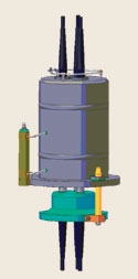
Amerada Hess' installation in Ceiba field offshore Equatorial Guinea, Africa, is a good example. There are now six pumps in operation, the most recent of which were installed within the past year. They are typically in water depths of about 2,500 ft and pump to an FPSO more than 4 mi away. Framo was the supplier. These pumps are of helico-axial design, Fig. 1.
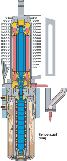 |
Fig. 1. Framo's design for helico-axial multiphase pump.
|
|
A new system, called WellAmps, has been developed under a JIP that is coordinated by Curtiss-Wright EMC and Petrobras. The JIP also includes BP, Marathon and ChevronTexaco. As the culmination of nearly 10 years' work, the WellAmps system (the pump, itself, is the SBMS-500, Leistritz MPP twin-screw pump, Fig. 2) is part of Petrobras' PROCAP 2000 goals. It is scheduled for installation on P-20, in about 3,000 ft of water, in Petrobras' Marlim field mid-year 2005.
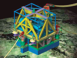 |
Fig. 2. The SBMS-500 multiphase pump scheduled for Petrobras' Marlim field mid-year 2005.
|
|
Another new system, the MultiBooster, is being developed by AkerKvaerner. The multiphase pump is scheduled for installation in 450 ft of water in Balmoral field on the UK shelf, perhaps by year-end. The twin-screw, Borneman-designed pump (Fig. 3) was part of Norway's DEMO2000 and included electric-motor contributor, Flender-Loher.
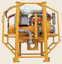 |
Fig. 3. AkerKvaerner's twin-screw multiphase pump, the MultiBooster, is to be installed in 450 ft of water in Balmoral field.
|
|
SUBSEA SEPARATION
The prospect of separating well fluids on the seafloor has some immediate advantages – provided that it can be accomplished reliably and at an acceptable cost. Separators often require maintenance (cleanout) and weirs sometimes need adjusting. By its very nature, subsea equipment must be able to go several years without maintenance, and remote monitoring and adjusting systems carry their own set of problems. This is probably why they have been slow to be developed.
Still, water that can be separated and re-injected at the subsea wellhead doesn't have to be pumped or otherwise dealt with at the surface. Removal close to the wellhead is highly beneficial, increasing production drive and relieving liquid load on the host facilities, including any scale tendencies. And the gas can be separated and re-injected, or if sufficiently dried and shipped to a pipe line from the seafloor, the remaining oil becomes easier to deal with.
Field experience and development status. There are two ongoing field examples, as well as some promising developments in various stages of research.
The Troll C subsea separation station is the only full-sized, installed and operating gravity-based subsea separator. It has been in operation since 2000. It is an oil/ water separator with the water re-injected. A gravity separator is a simple, reliable and proven device. It would be desirable to apply its operating principles in water depths greater than Troll's 1,100 ft. However, in deeper waters, high ambient pressure causes the wall thickness to be large, creating fabrication, handling and installation problems. But this is not prohibitive.
One could choose simply to accept the additional wall thickness and weight by using large lifting vessels. In addition, smaller diameters, generally, will give thinner walls. To compensate, one could increase the separator efficiency (i.e., reduce retention time). Finally, an electrostatic field can be applied to the oil and water mixture, using electrostatic coalescence and di-electrophoresis effects to accelerate droplet growth and separation.2 Thus, although the separator may get longer, thinner and have thicker walls, gravity separators remain good candidates for much deeper water applications, Fig. 4.
 |
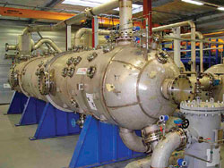 |
Fig. 4. Subsea separator, designed by FMC Kongsberg Subsea and CDS Engineering. Qualification work (bottom) in collaboration with Statoil. Line across top is for gas bypass.
|
|
Petrobras' VASPS (Vertical Annular Separation and Pumping System) is another existing subsea installation. It is in use in Marimba field, offshore Brazil. The two-phase gas/ liquid separator went onstream in 2001. It is installed in a 30- to 36-in. conductor pipe sunk into the seafloor, adjacent to the riser base.
The device comprises a pressure housing (six joints, each 39 ft long with 26-in. dia.) and the helix (six joints, 12-1/2-in. dia.), Fig. 5. At the bottom is a conventional ESP with shroud. At the top are conventional subsea tree, casing and wellhead components. Detailed information is available.2
 |
Fig. 5. Schematic showing how the VASPS system works.
|
|
Raw fluids are delivered from the subsea manifold to the VASPS unit. After separation, gas flows to the surface under its own power, while the ESP pumps the liquid to surface. The system allows cost-effective trade-offs. Because the multiphase wellstream is not separated until near the surface platform, only one pipe line needed. Also, electrical power losses from long umbilicals are avoided. Finally, the VASPS unit can be pulled easily for repair and maintenance.
Twister is a new, unique subsea separation device. More accurately called a dewpointer, it allows for water removal within a somewhat limited range. It uses a pressure drop to create supersonic flow speeds and subsequent ultra-low temperatures. This in turn, leads to water separation, Fig. 6. Because of that pressure drop, it will hasten the time of field abandonment, much like long flowlines do. Although it can be designed to remove varying amounts of liquids, including dewpointing, if the wellstream has too high a liquid/ gas ratio, some sort of rudimentary liquid knockout will be required.
 |
Fig. 6. Operating principle of the Twister.
|
|
The device requires a gas reservoir that has the right characteristics to allow its use. When these are present, the benefits are a simple, robust, no-moving-parts dewpointer that can save money. A topsides version, the first ever, became operational less than a year ago on Shell's B11 PA development project offshore Sarawak, East Malaysia, with a design capacity to dehydrate 600 MMcfd of non-associated gas (see World Oil, August 2002 and April 2004 issues).
Twister BV and FMC completed a feasibility study of the technology for subsea applications. No fundamental problems were identified, although several components will need further development and qualification prior to installation and operation on the seabed. The companies and various other partners have secured an EU subsidy for a four-year development program. This should result in the design, construction, installation and testing of the first pilot, subsea gas processing installation by 2007.
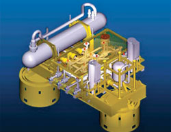
Complete modular systems. AlphaPRIME is approaching the end of a long road. After nearly 15 years, the Shell/ Alpha Thames consortium probably has the most complete of the all-in-one subsea production systems now brewing. It is a modular system approach that contains all of the seabed installation's operating parts, Fig. 7.
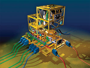 |
Fig. 7. AlphaPRIME complete subsea system for Shell.
|
|
The first stage was the completion of a preliminary, 15-month qualifying program. Although the system consists almost entirely of proven components, it has been necessary to test and approve two new valve actuators and a wet mateable power connector (see sidebar). The first stage of this testing has been completed, and the program is developing and testing additional components, and further enhancing some existing Shell-specified components. The new electric valve actuators have been qualified through the program, and the entire system has been verified by DNV to agreed standards and established as “catalogue ready” for use in Shell Operating Units worldwide.
A field using the system will deploy an all-electric System-Modular installation known as an AlphaCPU (Central Processing Unit). Located close to the wells on the seabed, each installation comprises at least two operating System-Modules of a size appropriate to the field throughput requirements. They are mounted on a KeyMAN manifold that has no active components or controls. Each compact System-Module contains all of the pumping/ boosting, processing, power and control equipment needed for efficient operation of the field.
“We are going down the path of further component development and testing, and now want Alpha Thames to work on the next generation of these products,” explained Ricardo Rodriguez, director of investments for Shell Technology Ventures. “This will include further testing of the high-voltage, wet mateable connector, the AlphaCPU control system and the CPU power distribution unit. The units are working beautifully, but we now want some of them tested to 3,000-m water depth equivalent and others to destruction,” he explained. “Shell and Marco Fabbri, one of the industry's foremost experts, are working with their partner to prepare the AlphaPRIME technology for near-term deployment on a producing field.”
Because they are modular, self-contained units, the field operator can quickly recover an entire System-Module whenever necessary, whether to add equipment to accommodate changing field conditions, to introduce new technology, or to overhaul existing components. Since the units are typically installed in pairs, one entire System-Module may be recovered, leaving the other on the seabed to maintain production.
Each slot on the KeyMAN uses an identical interface, so different or identical System-Modules can be fitted next to each other, in any order, regardless of function.
Because many fields do not see increased gas or watercut until later in their lives, using System-Modules enables the field operator to control initial capital expenditure, eventually installing boost, separation or injection capabilities when they are needed. This flexibility is not as readily available with other seabed technologies.
Ian Ball, head of Shell's Subsea – to-Beach, subsea processing technology maturation program (S2B), said, “We have been very pleased with the way the component qualification program has gone. Shell specialists believe that the greater water depths, from which hydrocarbons are now being recovered, have accelerated the need for this technology. By enabling oil and any produced gas or water to be separated and/or boosted on the seabed, productivity of certain reservoirs can be significantly increased.
“We now also have the technology to separate the water phase near the subsea wellheads and typically re-inject it back below the reservoir from which it came. It is thus possible to ensure that risers and export pipelines work at their full capacity, carrying only oil, gas or condensate. Boosting these fluids back to the host facility can also be provided in either multiphase pump, or in combined separation and single-phase liquid pump System-Modules, and reconfigured to whatever the field conditions require at any time during the field depletion life.”
The present design is being rated to a 10,000-ft water depth. The weight of the System-Modules and other components makes them straightforward to install using vessels of opportunity, supported by one or more ROVs.
| |
Gas-filled HV connector for seabed power supplies
|
|
| |
A unique, wet mateable high-voltage connector has been developed by Alpha Thames that uses nitrogen insulation. The ELEx connector is believed to be the first gas-filled wet mateable connector. It was developed to meet the need for dependable power supplies to the AlphaPRIME unit, at up to 5 MW at 11,000 volts. The new connector has been developed to perform repeated make and break cycles.
The new connector consists of a three pin male plug and a corresponding female socket. The plug has been designed for permanent installation on the seabed structure. The socket will typically be integrated within an AlphaPRIME System Module that contains the equipment requiring the power. Once the socket has been connected to the plug and sealed, a pressure chamber is formed. A Fluid Exchange Mechanism (FxM) removes the sea water from the chamber, cleans and conditions the electrical contacts and secures the contact area in a dry, inert gas at 3 bar. Continuous monitoring for water ingress during the life of the connection provides a warning of potential failure and enables the FxM to be activated remotely to remove the water before problems arise.
Studies had revealed that oil-filled connectors may be insufficiently reliable for long-term, continuous rated use due to the difficulty of eliminating impurities within the oil, which can lead to premature failure. Regular replacement of the oil by ROV can be expensive, but by using gas insulation, the plug and socket connections are maintained in a dry environment, free of impurities. The present system has been design rated for 3,000 m and has been successfully tested at depths down to 1,500 m. If required, the ELEx design can be scaled-up to provide dependable connections for up to 33,000 volts.
|
|
|
|
|
|
COMPRESSION MODULE
A subsea compression module is being developed by GE Power Systems Oil & Gas and Kværner Eureka. Subsea compression can supply a missing link that offers a way to get at resources that were previously not economic to recover, making development of several offshore gas fields profitable by eliminating the need for new platforms. Called BLUE-CTM, the subsea unit will be connected to shore or distant platforms through subsea flowlines. By installing subsea gas boosters close to the wellhead manifolds, production can be extended several years.
The module consists of a centrifugal compressor driven by a gas-filled electric motor and gearbox, stacked in a vertical orientation and packaged in a single sealed housing. The housing is filled with a gas sealant that separates the compressor lube oil from the process gas to prevent oil migration and, consequently, oil consumption.
The sealant gas can be an inert gas supplied from the platform through the umbilical or conditioned (separated and cooled) process gas extracted from the compressor discharge.
The module is equipped with coolers and scrubbers to control seal-gas dew point, and to avoid water and hydrocarbon condensation inside the motor, gear and lube oil system. In this way, corrosion, H2S embrittlement and lube-oil dilution is completely avoided, and reliability is maximized.
A gas-liquid separator system, which includes a scrubber, protects the compressor from liquid slugs, keeping the size and concentration of droplets well within acceptable limits. The scrubber architecture and design are conventional, except for the flow areas that are oversized to increase residence times, to maximize separation efficiency.
Technical challenges associated with highly reliable operation of an unattended compression module have been resolved through creative engineering solutions, e.g., the elimination of dry gas seals through the use of a gas-filled motor.
Compression modules will be made in a power range of less than 1 MW up to 12.5 MW. The pressure and flow ranges are the same as for conventional natural gas production applications. The development program is entering into the final verification phase that will culminate in the qualification of the module in a subsea field test. The project is financed through DEMO2000, Kværner and Nuovo Pignone. So far, over US$20 million has been spent.
The program has achieved two fundamental goals: feasibility of reliable subsea compression through 2,000 hr of extensive testing of a 850-kW unit (Fig. 8), and development of a 2.5-MW module, which was displayed at ONS 2002. A 12.5-MW module is to be built and then tested in a subsea field. In parallel with the qualification of the first generation BLUE-C compression production module, advanced R&D is being conducted on the development of an oil-free unit design, using magnetic bearings to further simplify operation of the module.
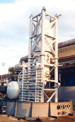 |
Fig. 8. The 850-kW subsea compressor module prototype.
|
|
CONCLUSION
Recovery factors need improvement in subsea, particularly deepwater fields. Considering that subsea fields keep aging, and technology keeps advancing, there will continue to be investment in technologies that essentially put the processing platform on the seafloor. The near future should see increased use of multiphase pumps, including some downhole versions, and subsea separation and compression. 
LITERATURE CITED
1 Devegowda, D., and S. L. Scott, “An assessment of subsea production systems,” SPE ACTE, 5 – 8, October 2003.
2 Michaelsen, J., “Innovative technology for ultra deepwater gravity-based separators,” OTC 15175, 2003 Offshore Technology Conference, Houston, Texas, May 5 – 8, 2003.
3 Vale, O. R. do, et al., “VASPS installation and operation at Campos basin,” OTC 14003, 2002 Offshore Technology Conference, Houston, Texas, May 6 – 9, 2002.
|