Offshore Technology Report
Deep-Shelf and ultra-deep well challenges
Reviews of two deep-well active areas in the Gulf of Mexico illustrate problems operators face in developing worthwhile reserves in these new frontiers.
Robert A. Meize, Anadarko Petroleum Corp., Houston
Offshore drilling continues to be very challenging and cost intensive, where $50-million wells are not uncommon. This article discusses deep-shelf drilling and completion challenges. It reviews two active areas for Anadarko Petroleum Corp. – Grand Island (GI) 116 “Hickory” Shelf subsalt field at a water depth of 328 ft, and Green Canyon 518 deepwater subsalt field at a water depth of »4,000 ft. It also shows a number of other fields Anadarko has been working for the last 10 years, Fig. 1. Almost all of these fields have wells drilled to depths below 15,000 ft. They all had to deal with multiple casing strings, depleted sands and demanding directional solutions to connect multiple stacked pay sands.
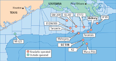 |
Fig. 1. Anadarko wells GC 518, GI 116 “Hickory,” and other company- or outside-operated offshore GOM fields.
|
|
INTRODUCTION
Over the past several years, offshore well depths have increased considerably. Fig. 2 illustrates this trend from 1993 through 2003. In 1993, industry was already drilling wells below 15,000 ft – today, those depths are approaching 30,000 ft. This trend is likely to continue as the search for hydrocarbons stretches into deeper water and/or deeper geologic horizons. The good news is that hydrocarbons are being found at these greater depths.
 |
Fig. 2. Anadarko and Union Pacific Resources GOM wells and maximum depths.
|
|
Fig. 3 shows that the number of GOM wells drilled per year has dropped somewhat, from a high of 1,289 in 2000, to just 795 in 2003. By comparison, Fig. 4 shows that only 10% of the Fig. 3 wells were drilled below 15,000 ft in water depths less than 2,000 ft, through 2002. A comparable figure for wells drilled below 20,000 ft would be less than 1%. This tells us two things: 1) there are relatively few exploration efforts at these depths; and 2) most everyone knows the difficulty and expense associated with these efforts.
 |
Fig. 3. Number of GOM wells drilled by industry, 1993 through 2003.
|
|
 |
Fig. 4. Number of GOM wells drilled in < 2,000-ft water to >15,000-ft TD, 1993 through 2002.
|
|
DEEP WELL DESIGNS FOR HICKORY
Drilling deep subsalt wells on the shelf typically requires seven to eight casing strings – as illustrated in Fig. 5 – run with tight tolerances and usually hard-to-get, good cement jobs. The GI 116 field has more than 10,000 ft of salt, and well depths below 22,000 ft. The first well was drilled from a jackup, followed by a delineation well drilled by the same rig. The third and fourth wells were drilled with a second-generation floater. Table 1 lists the pros and cons of each drilling vessel type.
 |
Fig. 5. Example GOM Grand Isle 110 A-5 well completion, in 323-ft water, to 22,000-ft TD, with seven casing strings.
|
|
| |
Table 1. Deep well design considerations for Hickory |
|
| |
Jackup pros
|
|
| |
• |
Hook load/ variable load combinations |
|
| |
• |
Working from existing infrastructure |
|
| |
• |
Conventional drilling in shallow geopressure |
|
| |
• |
Land large casing strings on bottom |
|
| |
• |
Easy access to BOP repairs |
|
| |
Cons
|
|
| |
• |
Alignment problems with big casing strings |
|
| |
• |
Casing annulus isolation for temporary abandonment |
|
| |
• |
Limited supply for year-round, open-water projects |
|
| |
Floater pros
|
|
| |
• |
Subsea wellhead systems for casing annulus isolation |
|
| |
• |
Faster BOP handling |
|
| |
• |
Needed for 350 ft+ water depths |
|
| |
Cons
|
|
| |
• |
Usually requires “pump-and-dump” |
|
| |
• |
Requires upgraded second, third or fourth generation rig |
|
| |
• |
Limited availability of rigs and landing strings with proper load combination |
|
|
A composite of time curves for the five field wells is shown in Fig. 6. The first well was drilled from a jackup with water-based mud. The second well was drilled with the same rig using synthetic-based mud and PDC bits. The dramatic difference is a technological breakthrough for subsalt drilling. With good knowledge of mud weights and frac gradients below salt, there was a lot of confidence to use synthetic-based muds. Drilling rates and hole stability were dramatically improved without any substantial mud losses.
 |
Fig. 6. Composite time curves for five GI Block 116 “Hickory” wells.
|
|
Wells 3 and 4 were drilled from a floater and were the fastest for the field. Well 5 was drilled from a jackup over the platform after two years of production. Some of the noticeable flat spots and one by-pass sidetrack are due to dealing with depleted sands. Differential pressure through the payzones ranged from 1,200 psi to more than 4,000 psi.
WELL CONSTRUCTION PHILOSOPHY
When designing these wells for completion, the company went for every engineering solution that would yield the perfect well. The old Chinese philosopher Confucius said, “The enemy of good is perfect;” – we were the victims, to some extent, of that enemy. Wells were completed with cement behind pipe as high as possible. The casing was tested to maximum anticipated pressures.
However, the stress to the system with high-pressure tests and high flowing temperatures helped compromise completion integrity, resulting in sustained casing pressures on several wells. The full cement sheaths in the shallow tie-back also made it nearly impossible to pump into the affected annulus to intervene the pressure problems.
To obtain the maximum productivity from these wells, “frac-pack” technology was incorporated to complete the payzones. During this process, this exposed the payzones to heavy losses of ZnBr2. During production, scaling problems because of the zinc fluids required multiple acid treatments. This may have contributed to a shortened life of at least one of the wells.
The fifth well drilled from the platform shows one of the biggest difficulties facing deep drilling, depleted zones. The sands seem to respond well to treatment with various concentrations of lost-circulation materials. However, the sand/ shale boundaries seem to be the culprit for some of the high mud losses experienced in the deep portions of this well.
For future wells, the simple thing may be to drill to the top of the zone and set pipe. The depleted interval would be drilled with lighter mud weight, then cased with an expandable liner to preserve hole size. There is also a shallow weak zone above salt. This complicates well planning by requiring an additional string to isolate this interval as well. It is believed that the massive mud losses and proximity to existing wells makes this interval almost impossible to cure without setting casing.
ULTRA-DEEP CONSIDERATIONS
Looking at some of the ultra-deep wells being drilled in deep water, Shelf wells are pushing 20,000 to 23,000 ft, but some of the deepwater wells are now exceeding 30,000 ft. This provides some insight into what to expect with deep-shelf drilling. Anadarko is currently drilling in the Green Canyon Block 518 area. The well sketch in Fig. 7 shows the basic casing program for the field.
 |
Fig. 7. Basic casing program for wells being drilled in GOM GC 518 field, in »4,000-ft water.
|
|
As with a lot of these developments, there is a thick salt section in excess of 12,000 ft--- the old “good news, bad news.” For these wells, over one-half of the well is salt and water. The other half is geopressure above salt and a pressure regression below salt. The wellbore sketch in Fig. 7 shows the complexity of the design. At least two or three of the casing strings required to drill these wells are in excess of 1,000,000 lb. This is at the limit for most rigs, and typically does not allow much overpull during casing running operations.
A compilation of drill times is shown in Fig. 8. The general trend is a logarithmic nature as the wells reach depths below 25,000 ft. This is due to the extra time required for trips, slower penetration rates, circulation times and logging operations at these depths. All these take considerably longer below 20,000 ft. Some interesting learnings are summarized in Table 2.
 |
Fig. 8. Compilation of drill times for GC 518 wells in »4,000-ft water, with six wells below 25,000 ft.
|
|
| |
Table 2. Special challenges for the ultra-deep
|
|
| |
• |
Drill pipe: High torque connections, joint strength |
|
| |
• |
Fishing: Back-offs, rotary table torque vs. drill pipe torque |
|
| |
• |
Wireline tools: Capstan and line size |
|
| |
• |
Hole volumes: Riser, full hole |
|
| |
• |
Hydraulics: TD pressure, HSI, bottoms up time |
|
| |
• |
Trip times |
|
| |
• |
MWD tool pressure limits |
|
| |
• |
Pressure @ 27,000 ft |
|
|
Drillstrings designed to handle running loads and drilling requirements may need special modifications to the BOP stack for shearing requirements. High torque connections necessary for drilling are not conducive to fishing operations. Most rigs cannot hold enough torque for conventional back-offs below 18,000 to 20,000 ft. This leaves fishing operations subject to severing tools that have limitations at these depths as well.
Wireline tools and equipment are limited at these greater depths. Special consideration must be made to hole conditions and wireline strengths. Side-entry subs for drill pipe-conveyed logging may not be rated much over the actual string weight at these depths. Hole volumes reach 4,000 to 6,000 bbl, making mud swaps logistical nightmares. Bottoms-up times can easily reach over half a day.
Hydraulics at this depth degrade considerably. Even with 4,000 to 5,000-psi standpipe pressures, pressure at the bit may only be around 500 psi. Equivalent circulating densities may exceed 1 ppg. Trip times for tools can approach one day each way. Measurement-while-drilling tools must be set to handle long hole sections with large changes in pressure needs during the drilling section. Lastly, downhole pressures can vary tremendously with just one or two tenths of mud weight.
SUMMARY
Deep well drilling poses a number of challenges to the drilling community. However, operators are finding respectable reserves in these new frontiers. They will need everything they can get from drilling rigs, including deck space, variable deck loads, hydraulics and off-line capability. The engineers need to run full-cycle, well-construction models to understand all drilling and production loads. Cement requirements and subsequent pressure testing must be carefully planned. The good news is that the industry is finding more substantial reserves in these deep plays, creating more opportunities for everyone. 
ACKNOWLEDGMENTS
The author would like to thank the management of Anadarko Petroleum Corp. for permission to share this work. He also thanks Willie Iyoho and the GOM staff for their contributions. This article basically represents a presentation made by the author in the session, “Deep gas on the GOM Shelf: The potential and the challenges,” at the IADC Drilling Gulf of Mexico Conference & Exhibition, Houston, December 9 – 10, 2003.
BIBLIOGRAPHY
Iyoho, A., R. Meize and K. Milheim, “Lessons learned from integrated analysis of GOM drilling performance,” paper 16290, 2004 Offshore Technology Conference, Houston, May 3 – 6.
THE AUTHOR
|
| |
Robert A. Meize, division drilling manager for offshore Gulf of Mexico, Anadarko Petroleum Corp., holds a BS degree in petroleum engineering from New Mexico Tech and a masters degree in business administration from Oklahoma City University. He has over 25 years' drilling and production experience in offshore and onshore operations, having worked areas in West Texas, Rocky Mountain, Mid-Continent and Gulf Coast regions. After a career with Arco, he joined Anadarko in 1994, where he has been involved with developments in subsalt, deep water and shelf drilling.
|
| |
|
|

