Close tolerance liner drilling and requirements for deepwater
Offshore Technology ReportClose tolerance liner drilling and requirements for deepwater applicationsComponents for Close Tolerance Liner Drilling operations have been designed, built and tested in a full-scale onshore well simulating most aspects of an offshore well.Ken Smith, ConocoPhillips, Inc.; Bruce Houtchens, Tesco Corp.; George Givens, Baker Hughes Inc.; Greg Bailey, Grant Prideco, Inc.; and Doyle Reeves, Hunting Energy Services, LP Deepwater drilling operations in the Gulf of Mexico (GOM) are some of the most difficult and expensive in the world. Many of these operational challenges may be overcome if advantages realized with casing while drilling in South Texas translate to the deepwater environment. ConocoPhillips, Inc., Baker Hughes Inc. and Tesco Corp. have jointly pursued this by developing a Close Tolerance Liner Drilling* (CTLD) system for application in the deepwater environment. This article describes the CTLD system and some of its unique operational aspects. It also discusses requirements of the flush- or near-flush-joint liner connections for liner drilling operations, and how the ability to meet those requirements was demonstrated. And results of the CTLD system testing program to demonstrate its readiness for offshore application are discussed. This article was prepared from the presentation of the same name presented at the World Oil 2004 Casing While Drilling Technical Conference, Houston, March 30 – 31, 2004.1 INTRODUCTION A tight operating window between fracture and formation pressure characterizes GOM deepwater drilling. The consequence is that as many as seven, eight, or more, casings may be needed to reach deep drilling objectives. Industry has become adept at managing the balance of mud weight, equivalent circulating density (ECD), trip margins, lost circulation material treatments and other operational aspects to try to push the casing points. However, this balance is difficult, and problems occur frequently. These wells are inherently expensive, and typically are budgeted for US $40 to 50 million. However, when problems occur, they can be extensive, and cost overruns commonly approach 50% and more. A few GOM wells have exceeded $100 million. Toward the other end of the drilling cost spectrum, ConocoPhillips operations in South Texas are frequently characterized by massive lost circulation. Many wells have been lost as a consequence. Tesco's Casing Drilling* operations were introduced in 2001, and lost circulation, stuck pipe and well control issues have all but disappeared on those wells. This was an unexpected benefit, but clearly one that has tremendous potential in the deepwater environment. Accordingly, in early 2003, ConocoPhillips, Tesco and Baker Hughes jointly embarked on extending the onshore Casing Drilling technology offshore to deep water. DEEPWATER LINER DRILLING DESIGN AND CANDIDATE SELECTION A typical deepwater casing program for a 25,000 to 30,000-ft MD well might be:
Each hole interval has its own challenges, and most can benefit from some form of Casing Drilling technology. Generally, the hole intervals through the 13-5/8 in. do not experience many problems. The goals here are generally associated with reducing drilling times. Deeper hole intervals are generally more problematic, especially if the well is drilled through a massive salt section. The primary goal in these intervals is risk reduction. The interval immediately below salt is the one that has cost ConocoPhillips the most significant cost overruns. This interval is where the 11-3/4-in. liner is set, so this string became the initial candidate for CTLD. For this application, the design basis for CTLD agreed upon would provide for:
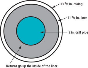
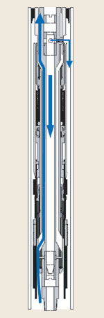
OVERVIEW OF CTLD OPERATIONS After agreeing on the specific liner that would be targeted and the environment it would be set in, it was necessary to agree generally on how drilling/ cementing operations would be done. Several operational scenarios were discussed, each with its consequential impact of CTLD system complexity. It was agreed that a two-trip system would be developed. This met the objectives of quickly getting the well cased off, and keeping tool complexity to a minimum. An outline of this plan is: Trip 1: 1) drill the hole interval; 2) hang the liner; 3) set the liner top packer; and 4) pull out of the hole. Trip 2: 1) run in the hole with cement retainer; 2) close BOPs and test liner top packer and cement retainer; 3) squeeze cement; and 4) pull out of the hole. CTLD CONFIGURATION There are significant differences between onshore Casing Drilling operations and subsea liner drilling. Onshore, casing is in the rotary table. The BHA, consisting primarily of an underreamer and a pilot bit, latches into the bottom joint of casing and extends below the casing. The casing is used as the “drillstring,” and returns are taken up the casing-openhole annulus. In subsea drilling, all casing is at or below the mudline, and drill pipe is in the rotary table. Therefore, all casings are effectively “liners,” and drill pipe will extend to at least the liner top. Due to the clearances between casings in the deepwater GOM, it is impossible to circulate drilling mud and cuttings up the annulus between two casings, Fig. 1. Instead, the drillstring/ BHA must extend through and out the end of the liner so that mud and cuttings can be circulated up the inside of the liner between the liner and drilling assembly.
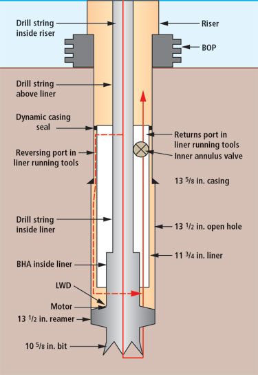
This unique circulation path is shown in Fig. 2. Mud is pumped down the drillstring, through the BHA, and then up through the liner ID and out the top through a bypass area built into the liner hanger running tool. At the top of the liner, a small portion is diverted down the liner backside through a reversing port.
This ensures that the open hole stays flushed of any cuttings or well fluids. Friction pressures down the liner and casing overlap interval are quite high, so Tesco's Dynamic Casing Seal* (DCS) element was developed for the liner top, to ensure that fluid goes down the backside rather than up into the casing above the liner. There is one low-risk, yet high-consequence, safety issue that had to be addressed in tool design. There is a slight possibility that a kick will be detected when the liner, along with the encased drillstring, is across the BOP. Because the mud return flow bypass area goes through the inside of the liner, any influx would go directly into the drilling riser above the BOP. Most BOPs are not capable of shearing both the liner and the drillstring, so an Inner Annulus Valve (IAV)* included by Baker in the design of the tool could shut off this internal flow after the BOP was closed around the liner. This configuration leads to several realizations, all of which impact system design and operational considerations:
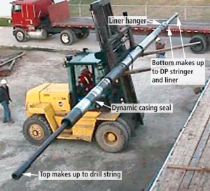
SYSTEM COMPONENT DESCRIPTIONS/ TESTING The CTLD system comprises several components that had to be designed in an integrated manner. Each component needed to be tested in the shop environment, and then finally as a system in an onshore test well, before it could be confidently deployed offshore. At the top of the CTLD system is the Dynamic Casing Seal (DCS) element. Below that are the Hy-Flow* running tool and the liner hanger. This assembly makes up both into the liner and into the drillstring running through the liner, Fig. 3.
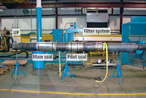
DYNAMIC CASING SEAL One critical component of the system is the DCS element, Fig. 4, that is positioned above the liner and hanger. This element must seal the small annular space between the 11-3/4-in. liner and the 13-5/8-in. string, yet allow the drillstring to extend through the middle while carrying full hook load. In addition, it must slide, rotate and seal while tripping and drilling.
The return-fluid circulation path is up the inner annulus between drill pipe and liner ID. The seal must also contain the pressure of circulating a low rate down the backside of the 11-3/4-in. liner with up to 5,000 ft of overlap with the 13-5/8-in. casing. Additional design objectives for this tool required it to survive the trip in the hole prior to drilling ( ˜ 10,000 ft), and rotate and drill for an interval of up to 5,000 ft, which includes about 300,000 revolutions of the drill pipe and liner assembly. Mud properties were planned to match recent GOM drilling experiences. This interval requires a weighted, synthetic-based system, and medium temperature with minimal lost circulation material as a background concentration, with occasional pill additions as required. The tool concept, when finalized, incorporated a pilot seal, main seal and rotational elements that were subsequently separated to simplify testing and isolate critical components. Translating, or sliding of the DCS element required a design that did not wear out and yet held pressure while tripping and drilling. A bearing assembly allowed rotation, and a filter system kept drilling fluid solids from damaging the seal or bearing assembly. Shop testing began on a scale version of the translating seal assembly that was tripped for 19,000 ft while under pressure. Rotational testing was accomplished with a full-scale model run under high pressure with weighted synthetic-based mud and elevated temperatures. This testing proved the durability of the bearing assembly. Attempted plugging of the device with lost circulation material was the final test for this tool. These tests proved that all DCS components met all design criteria. Key learnings were incorporated into the prototype tool used for the subsequent full-scale CTLD system tests. More details of the shop testing program are available in the original paper.1 The DCS element is mated to the Baker Hughes Hy-Flow liner hanger running tool with a common thread that locks it in rotation. Again, the load path is through the inner drill pipe string passing through the ID of the DCS element. LINER HANGER AND RUNNING TOOL
The liner hanger, running tool and DCS are all integrated into one assembly. The liner hanger is a field-proven, Baker Inline* hanger/ packer modified for vigorous rotation. It is attached to the running tool assembly so that all rotation at surface is transferred through the running tool into the liner hanger and liner. Setting of the hanger is accomplished with hydraulic pressure isolated from the hanger until time of setting. The running tool assembly provides critical functions that are essential to success of CTLD operations. The integrated assembly allows fluid flow to be directed through the tool and BHA in a conventional manner, while diverting a small portion of flow to the annulus above the liner hanger system, Fig. 5. Fluid flow diverted to the annulus continues down the openhole annulus and commingles with the fluid exiting the BHA. Returns are taken up the inner annulus between liner and drill pipe inner string. The path of return fluid through the running tool is achieved with a concentric flow area internal to the tool, isolating critical mechanisms from fluid flow. The inner annulus flow area can be selectively closed and opened by means of the Inner Annulus Valve (IAV).* A second valve is integrated into the design to control fluid that is diverted or “reversed” to the annulus. Both the IAV and the Reverse Circulating Valve remain open during drilling operations. Sequential closing of the valves is accomplished with left-hand pipe manipulation, as required. Releasing the running tool from the hanger is accomplished with hydraulic pressure that is mechanically isolated from the running tool until time of release. An extrudable ball seat placed in the tool ID allows the use of either a ball or drill pipe dart to pressure against for hanger and running tool activation. Once activated, the ball or plug is pumped through the extrudable seat and circulation is re-established. After releasing from the liner hanger, the running tool is picked up a few feet, freeing some dogs to allow setting down on the liner and compressing the ZXP* liner top packer. At this point, the well is mechanically cased off, and drill pipe and BHA are tripped out. Then, the cement retainer is tripped in and the well is cemented. Specific design features were incorporated to address anticipated drilling dynamics not normally associated with standard liner systems. Significant redundancy is designed into the system to allow for multiple activation methods, as detailed further in the original paper.1 Lab testing of components and new mechanism designs was extensive. Valve mechanisms have been cycled repeatedly to assure functionality. Critical components subject to fluid erosion were placed in a flow loop and subjected to 14.5 ppg mud flow for 170 hr at 12 bpm. 11-3/4-IN. INTERMEDIATE DRILLING LINER Due to the tight clearances with the 13-5/8-in. casing ID, the 11-3/4-in. intermediate drilling liner will have an integral flush or near-flush connection. Additional application requirements for the 11-3/4-in., 65-lb HC Q-125 are listed in the original paper.1 Flush and near-flush-joint casing suffers from the stigma of being relatively weak, so there was concern about its ability to endure loads encountered during drilling operations. However, design tools such as Finite Element Analysis, more sophisticated test equipment, and improvements in metallurgy have played a major role in improving connection performance. Two connections were tested: one from Grant Prideco (DWC/A-DS) and one from Hunting (SLSF). These connections have design attributes that were felt to be favorable in the CTLD application. Connectors integral to the pipe improve the economics, compared to threaded and coupled connectors. As well, using one connector per joint reduces leak/ fatigue points compared to threaded and coupled. These connections have axial ratings that are less than the pipe body, but tensile capabilities of both connectors exceed expected tension range with safety factors above four. The connectors also feature negative load flank thread forms to enhance their tensile capacity and assembled rigidity by means of mechanical advantage using torque to pull mating members together, vs. pushing them apart.1 And, bi-directional sealing systems provide integrity from internal or external pressure. Tapered threads with coarser pitches allow deep stabbing and decrease operational deployment time. Fatigue from extended rotation was the primary concern. With improved chemistries, quality control and heat treatment methods, casing materials have been enhanced. The result is increased toughness and through-wall consistency. This decreases notch sensitivity reflected in improved fatigue performance. Product verification was still needed, so cyclic fatigue testing was performed to determine endurance limits for an alternating stress equivalent to a 5°/ 100-ft build rate.1 Previous static load tests conducted by the thread companies were also considered in the evaluation.1 Anaerobic thread lubricants and conventional Teflon-based “green” dopes were both tested and found to be suitable for CTLD applications. CONCENTRIC REAMER DESIGN The last component that needed evolution was the concentric reamer. The reamer selected was Smith's Rhino Reamer *. This reamer regularly opens a hole to about 20% more than the body OD; yet, to drill the 13-1/2-in. hole, a 30% enlargement was needed. Smith redesigned its existing reamer in a 10-3/8-in. OD body and extended the reaming blocks the additional length needed. These tools have been delivered and successfully run in two deepwater wells. In both cases, they were run to enlarge a previously drilled 12-1/4-in. hole. This is an inherently unstable configuration and is tough on the tools. However, they performed well. ONSHORE SYSTEM TESTING After successfully passing all lab and shop testing, the full-scale DCS and liner hanger and running tool were assembled and delivered to Tesco's test well in Houston for a cased-hole testing program. This well has 13-3/8-in., 54.5 ppf casing set to 2,214 ft in a deviated wellbore. The test had several objectives: 1) understand the hydraulics with the system; 2) determine whether rotational dynamics between the liner and the 13-3/8-in. casing are an issue; 3) subject the system to 10,000 ft of tripping, simulating an offshore well; and 4) subject the system to the equivalent of 3,000 ft of drilling rotational wear; and drill openhole. Clearly, after performing these tests, the liner hanger still had to set and the liner packer still needed to be able to be set and seal. All of these objectives were successfully achieved in the cased-hole test, completed in mid-February, 2004.1 The second phase of testing will focus on the last objective, drill open hole. This was to occur in April. The testing plan consisted of two parts. The first was a cased-hole test that targets the first four objectives. The second is an openhole test that targets the last objective of drilling openhole. The cased-hole test was successfully completed in mid-February 2004.1 ONSHORE TEST FINDINGS The initial cased-hole testing program yielded promising results on all fronts. The pressure information that was collected is now being used to help modify a widely used industry drilling hydraulics, surge and swab model to accommodate the unique flow paths of this system. The drilling mechanics package clearly demonstrated that vibrations due to rotation at moderate rpms were well within acceptable limits. This was a critical positive finding. The internal setting mechanisms of the Hy-Flow setting tool were found to be well isolated from the drilling fluids. Their integrity was proven when the liner hanger was returned to the shop, where the setting ball was dropped into the setting tool, which was pressured up, and the liner hanger was set. After a full teardown of the DCS, minor damage had been sustained by the leading edge of the pilot seal, but the seal was still functioning. The main seal displayed acceptable wear and functioned as designed. The rotational components of the seal showed minimal wear in the 100,000 revolutions and there was no evidence of plugging in any of the internal passages. Modifications to the pilot seal have been implemented and the tool is being prepared for the second phase of testing. Other test results are detailed in the original paper.1 Tripping is an unplanned event, and most tripping offshore will not involve laying down the liner. However, the liner connectors need to be robust enough to accommodate a trip and retain the makeup torque throughout subsequent drilling operations. The testing thus far has required two round trips of the liner. Torque monitoring was used on all makeups, and breakout torque was recorded. No breakout torque degradation was noted between two trips. The liner was inspected for damage after each trip. Most of the damage found was field repairable, and this was done before running the liner back into the well. A few joints required complete re-cut in the shop. Clearly, this suggests that, in an offshore setting, a connector representative needs to be on location during liner running. The testing concluded that the application is not limited by thread technology. Existing casing product lines, as well as those designed envisioning such applications, met project requirements. CONCLUSIONS The work done thus far on Close Tolerance Liner Drilling operations leads to several conclusions. The components necessary for this system have now been designed, built and tested in a full-scale test well onshore. The testing simulates most aspects of an offshore well. The Dynamic Casing Seal element is robust and fully meets the design requirements. The liner hanger has been demonstrated to be robust also. It was successfully set after the testing operations were completed. The 11-3/4-in. liner connections are not limiting. They fully meet the needs of the liner drilling. Operational adjustments are needed to implement CTLD, but they are not significant. And well control and well safety are fully addressed with the design and operation of the system. The one remaining test objective was to drill openhole. The results of this last objective were to be known by April 2004. In short, Close Tolerance Liner Drilling operations may very soon become an available alternative to fighting formation problems in deep water. There appear to be no show-stoppers at this time.
|
||||||||||||||||||||||||||||||||||||


- Coiled tubing drilling’s role in the energy transition (March 2024)
- Advancing offshore decarbonization through electrification of FPSOs (March 2024)
- Subsea technology- Corrosion monitoring: From failure to success (February 2024)
- Using data to create new completion efficiencies (February 2024)
- Digital tool kit enhances real-time decision-making to improve drilling efficiency and performance (February 2024)
- E&P outside the U.S. maintains a disciplined pace (February 2024)
- Applying ultra-deep LWD resistivity technology successfully in a SAGD operation (May 2019)
- Adoption of wireless intelligent completions advances (May 2019)
- Majors double down as takeaway crunch eases (April 2019)
- What’s new in well logging and formation evaluation (April 2019)
- Qualification of a 20,000-psi subsea BOP: A collaborative approach (February 2019)
- ConocoPhillips’ Greg Leveille sees rapid trajectory of technical advancement continuing (February 2019)

