Seismic Acquisition
Vertical hydrophone arrays solve challenges of transition zone seismic acquisition
A new method virtually eliminates ghosting during data processing by helping to separate the upgoing from the downgoing seismic wavefield.
Nick Moldoveanu and Mike Spradley, WesternGeco
Surface seismic surveys face numerous challenges when applied in shallow waters and marshes of transition zone areas. These challenges include reduced signal-to-noise ratio resulting from poor coupling of the receivers and strong ambient noise due to wind, surf and currents. Non-uniformity of the sedimentary layers below the water bottom can also induce signal distortions due to static shifts. Unconsolidated shallow sediments can cause attenuation of the seismic signal. Additionally, the signal can be contaminated with ghosts and water layer reverberations.
To overcome these challenges, WesternGeco developed and patented a method of acquiring seismic data from transition zones based on acquisition with vertical hydrophone arrays. This method virtually eliminates ghosting during data processing by providing the possibility of separating the upgoing seismic wavefield, which typically contains the useful seismic data, from the downgoing seismic wavefield that is reflected from the water surface, which results in ghosts and noise from water layer reverberations.
Technical solutions to ghosting include either burying or ramming the receivers and sources into the mud layer and the use of vertical hydrophone arrays. The technique has been tested successfully in the marshes of Texas and Louisiana and has also been commercially applied in a seismic data acquisition project in Argentina that included obtaining data from both land and underwater in a lake. In deeper waters, the technique was used to conduct surveys in obstructed areas around platforms or buoys that can't be reached with a streamer array.
TECHNIQUE DEVELOPED FROM STREAMER APPLICATION
The vertical hydrophone array technique was first developed by Geco-Prakla when it used an over/ under technique offshore to deploy streamers deeper in the water to obtain better data. However, when the streamer is deployed deeper from the surface, the ghost effect is more significant than if the streamer were near the surface. This is due to a greater delay between the real seismic signal and the ghost, which translates into a notch in the amplitude spectrum that affects the seismic bandwidth of the real signal, Fig. 1. When receivers are towed close to the water surface, the ghost effect is negligible because of the short interval from the water's surface to the top streamer. The notch in the amplitude spectrum corresponding to this ghost is at high frequencies and, typically, does not affect the useful seismic bandwidth, Fig. 2.
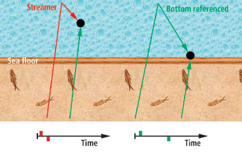 |
Fig. 1. Data is affected by receiver ghosts with bottom referenced receivers. Vertical hydrophone arrays could eliminate the ghost and attenuate the receiver-side reverberations.
|
|
 |
Fig. 2. The notch in the amplitude spectrum for a hydrophone deployed at a 30-m depth is at 25 Hz, and the notch for a hydrophone deployed at 8 m is at 93 Hz. The vertical seismic resolution is more affected by deeper deployed hydrophones.
|
|
The primary objective of deploying streamers deeper in the water was to be able to shoot in inclement weather, since the deeper the streamers, the less wave effect on them. When ghosting affected the data, a solution was developed to use a second streamer for over/ under acquisition. The noise from the receiver ghost was separated from the useful data during processing.
RAMMING RECEIVERS BELOW THE MUD
A significant difference of the vertical hydrophone array technique in the transition zone is burying or ramming the receivers and the explosive source. WesternGeco uses Vibra-Ram, a patented technology to mechanically drive a receiver or seismic charge to a pre-determined depth. This technique can be utilized in water depths up to approximately 20 ft through the transition zone. In shallow waters of the transition zone, the Vibra-Ram technology can be deployed from marsh buggies, air boats or shallow draft barges. Typically, an airboat is used in transition zones because it's easy to navigate and operate. The company also has used shallow draft barges.
In soft sediment, the receiver and/or explosive charge is driven to the predetermined depth. If harder or denser sediments are encountered, the unit vibrates to help penetration. The receivers and source are buried at about the same depth, resulting in better and more uniform data acquisition.
HIGHER-QUALITY DATA FROM DEEPER RECEIVERS
The traditional method of obtaining surface seismic data in transition zones was to place the detectors on the water bottom, but the problem is that they were subjected to numerous noise sources such as surf, wind, currents, cables and couplings. Charges were placed in drilled holes with limitations on time and cost for the effort.
With the vertical hydrophone array technique, it is necessary to have at least two receivers that are buried into the mud in the transition zone. Typically, the depth of the lower receiver is about 35 ft below the water line, with the second receiver about 12 ft above the bottom receiver, Fig. 3.
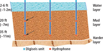 |
Fig. 3. With the vertical hydrophone array, it is necessary to have at least two receivers buried into the mud in the transition zone. Typically, the depth of the lower receiver is about 35 ft below the water line with the second receiver about 12 ft above the bottom receiver.
|
|
The vertical hydrophone array can also be used in deeper waters. In this case, the array consists of a single Kevlar-reinforced cable that is anchored on the seafloor by a 20 – 40 kg weight. Eight to 10 meters above the weight is a submersible float that ensures that the receiver array is vertical in the water. From the float, the cable goes to the surface and is attached to the radio telemetry buoy (DAU). To decouple the array from the surface, a bungee cord is placed between the float and the surface, Fig. 4. The response of each receiver is measured separately and transmitted to the recorder as separate channels.
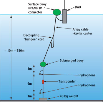 |
Fig. 4. The over/under array includes a Kevlar-reinforced cable anchored on the sea bottom. A submersible float 8 – 10 m above the anchor ensures a vertical receiver array. Over/ under receivers are spaced 6 – 8 m between anchor and float.
|
|
VERTICAL HYDROPHONE ARRAY ADVANTAGES
Two important advantages of using vertical hydrophone arrays in transition zones is being able to ram the receivers below the water bottom rather than setting them on the bottom as previously done with marsh phones. This technique results in less environmental noise. Also, with the use of marsh phones, the explosive source would have to be buried very deep into the mud and larger amounts of explosives would be necessary. With the vertical hydrophone array, the explosive source can be set with the same ramming technique. Smaller explosives are necessary since they are placed at about the same depth as the receiver, increasing the signal-to-noise ratio and resulting in cost savings to the customer.
A second major advantage is the development of over/ under receivers that improve data quality by making it easier to identify and remove the receiver ghosts as well as other noise from reverberations in the water layer. With the vertical hydrophone array technique, upgoing and downgoing seismic wavefields can be separated. This is possible due to the two-receiver array.
Another advantage to the vertical hydrophone technique is that this is a point receiver acquisition and it avoids the receiver array effects on the seismic signal: non-uniform coupling of the receiver within the array, and static and different travel times.
In addition to significantly improving the efficiency of the survey and data quality, the technique also reduces the environmental impact on the survey area.
FIELD TESTS
Tests were conducted in the Gulf of Mexico in both deep and shallow water to prove the feasibility of the vertical hydrophone array technique as an alternative to the four-component ocean bottom cable technique.
During a test in the West Bay area of Louisiana, a 3D swath was acquired to prove the feasibility of buried vertical hydrophone arrays. Both receiver and shot intervals were 165 ft. The source, six pounds of dynamite, was rammed to a depth of 50 ft. The hydrophones were rammed to depths of 20 ft and 35 ft.
The 3D stacks were produced for the hydrophone at 20 ft (the “over” hydrophone), for the hydrophone at 35 ft (“under” hydrophone) and after wavefield separation. There are different methods to perform wavefield separation using vertical hydrophone arrays. Here, a wave extrapolation algorithm developed by Lars Sonneland was used, Fig. 5.
 |
Fig. 5. The method described here is based on extrapolation of the seismic wavefield from one level to another level using the exact wave equation formulation; this is an exact 2D method.
|
|
Other tests were conducted in the Gulf of Mexico transition zone to compare responses of the hydrophones and geophones rammed at different depths: 11 ft, 20 ft and 35 ft. A 5-db improvement occurred between 20 ft and 11 ft, and a 7-db improvement was recorded between 35 ft and 20 ft with the hydrophones, Fig. 6. The improvement in signal-to-ambient noise from 11 ft to 35 ft was 7 db for the geophones, Fig. 7.
 |
Fig. 6. Tests were performed in the transition zone in Louisiana and Texas to determine the improvement of the signal-to-noise ratio (ambient noise) by ramming the hydrophones and geophones at different depths. Improvements of between 5 and 12 db were recorded for rammed hydrophones.
|
|
 |
Fig. 7. The improvement in signal-to- ambient noise ratio between the geophone at 11-ft and 35-ft depths was 7 db.
|
|
The seismic resolution was improved by attenuation of the ghosts and receiver side reverberation, and the signal-to-ambient noise was improved by the combination of over and under hydrophones.
FIRST COMMERCIAL TEST IN ARGENTINA LAKE
The first commercial use of the vertical hydrophone array proved the technique. It was performed in Argentina in the country's largest gas field, Lomo de la Lata, which sits atop a large lake that was formed when the Cuenca de los Barreales and Cuenca Mari Menuco canyons were flooded, Fig. 8. The operator wanted to investigate the extent of the gas field under the lake. However, only 2D seismic acquired in the 1960s was available. High-quality 3D data was necessary under the proposed drilling plan that included wells from shore to reservoirs below the lake.
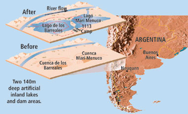 |
Fig. 8. The Cuenca de los Barreales and Cuenca Mari Menuco canyons in Argentina were flooded to make two lakes that sit atop Lomo de la Lata, Argentina's largest gas field where, YPF wanted to investigate the extent of field under the lake.
|
|
In this application, the 3D seismic survey was performed in the lake as well as on land. In the shallower regions of the lake, the vertical hydrophone array was installed with the ramming method. In the deeper portions (the lake was about 300 ft deep at its deepest point), the vertical hydrophone array was attached to anchors and dropped to the lake bottom.
A buoy attached to the cable kept the hydrophone array vertical, above an anchor. Radio telemetry equipment was installed on the buoy to transmit the seismic data (DAU), Fig. 4. While an ocean bottom cable method could have worked in the lake, the expense of deploying a crew and equipment prohibited that particular method.
One key advantage to using the vertical hydrophone array in the lake was that it allowed the crews to use the same system on land and in the water, resulting in a single seamless stream of data from both the land and the lake.
SUMMARY
The tests and commercial application of the vertical hydrophone array system have proven that the technology and technique can meet the various challenges of surface seismic in shallow water transition zones. The signal-to-noise ratio and seismic resolution is enhanced. In deeper water or hard-bottom waters, the bottom-referenced vertical hydrophone arrays can be used to attenuate ghosts and receiver-side reverberations. The technique can be successfully applied in under-explored transition zones or in regions where new 3D seismic surveys are required to replace older 2D acquisitions. 
THE AUTHORS
|
| |
Nick Moldoveanu is geosupport manager for WesternGeco in Houston with expertise in seismic acquisition, processing and interpretation. He has been with WesternGeco/ Geco-Prakla since 1989, most recently as technical advisor for North and South America reservoirs. He has also held positions as senior geophysicist and senior programmer. Prior to joining WesternGeco, he served as technical director of the seismic data processing center for IPGG, the Geophysical and Geological Oil Prospecting Co. in Bucharest, Romania. Mr. Moldoveanu holds a Master's Degree in mathematics and a Master's Degree in geophysics, both from the University of Bucharest.
|
|
Mike Spradley is a sales account manager for Transition Zones for WesternGeco, responsible for North and South America regions. His expertise also includes ocean bottom cable operations and planning. He previously was vice president of Sales and vice president of Transition Zone Operations for Terra Marine Engineering. Mr. Spradley's education includes the US Navy Electronics School in Memphis, Tennessee, and San Diego, California, and the US Navy Acoustics School in San Diego.
|
| |
|
|

