Drilling Report
Tailor lightweight slurry designs to well conditions and production plans
Reliance on standard solutions may result in casing cement-sheath failures and shorten a well’s productive life
Ron Crook, David Kulakofsky and James Griffith, Halliburton
More than ever before, operators and service companies planning lightweight oil- and gas-well cement jobs are giving attention to casing/cement sheath integrity for the entire life of oil, gas, geothermal and gas-storage wells.
Operating in fields where there is a risk of breaking through a weak zone during cementing naturally leads the cement job planner to seek ways to reduce the weight of the slurry used. However, future well operations may create stressful conditions that can destroy cement-sheath integrity, if the wrong sealant is selected.
Analysis of well characteristics, cement slurry properties, and behavior of set cement when it is under stress can lead to selection of a slurry that has the best potential to serve its intended purposes:
- Bonding to casing and to wellbore walls
- Isolation of well zones from one another
- Supporting and strengthening the casing string.
CEMENT SHEATH FAILURE
Casing cement-sheath failures can shorten the productive lives of many wells, resulting in output losses, remedial cementing expenses and well abandonment.1,2 Failure of the cement sheath around the well casing is most often caused by pressure- or temperature-induced stresses that accompany operations performed during the well’s economic life.
Fleckenstein et al reported several cement failure mechanisms resulting from finite element analysis (FEA) performed at the Colorado School of Mines:3
- The primary cement-failure mechanism is radial cracking of the cement sheath, caused by tensile, tangential stresses induced within the cement sheath.
- Tangential stresses within the cement sheath can be reduced significantly, if the cement is more ductile, with higher Poisson’s ratios and lower values of Young’s modulus. Brittle cements are more likely to develop significant tensile tangential stresses for a given loading condition.
- Cement-sheath radial cracking occurs at tangential, tensile stresses greater than 200 psi. Therefore, designing the cementing system to avoid such stresses will help prevent radial cracking of the sheath.
Two additional failure modes are destruction of the bond between casing and cement, and plastic deformation of the sheath.
Consequences of sheath failure can include: (1) loss of gas reserves; (2) unsafe operations; (3) premature water or cap-gas production; (4) cost of remedial operations; and (5) complete well shutdown to meet governmental standards. The prime contributor to cement-sheath failure is change in sealant stress level during the life of the well. Production, injection, depletion, subsidence and stimulation can introduce changes in temperature and/or pressure to cause the stress.4,5 Heating of water or mud left in the annulus is a major cause of cement-sheath stress.
Well-cementing planners can engineer selection of the most ideal sealant by considering the following:6,7
- Failure of well sealants can result from their stress condition, which in turn is dependent on the borehole condition, sealant shrinkage/expansion characteristics, and the sealant’s bond to the formation and casing. If the sealant is subject to compressive stress, it is more likely to fail in shear. Otherwise, tension is the most likely failure mechanism.
- If the sealant’s Young’s modulus is higher than that of the rock, the sealant is most likely to fail from tensile cracking when the pressure/temperature inside the casing is increased.
- Casing/sealant de-bonding processes are related to the presence of anisotropy and to the stiffness contrast between the sealant and the rock.
- Compressive strength, alone, should not be used for selecting a sealant. The sealant’s mechanical properties – Young’s modulus, Poisson’s ratio, tensile strength, shear strength and bonding strength – should also be established.
Most service companies provide simulation services that rely on PC-based programs to evaluate and predict the sealing capacity of cement jobs, using FEA. These life-of-the-well (LW) planning tools can help the engineer select, among several cementing scenarios, the sealant material that best meets structural and sealing requirements for the well under study. Selection is achieved by performing mechanical analyses of the completed well’s structural behavior at several points, and for several sealant choices. LW programs allow easy comparison of sealant performance choices for a specified well configuration.
To assess potential sealant damage, LW software simulates a well’s entire history, including borehole drilling, casing operation, cementing job, cement curing, completion and testing, production and injection. Extreme operations, like high-rate killing, fracturing, unloading and evacuation, are also simulated. Three load types are considered:
- Shrinkage or expansion of cement during curing
- Mechanical fluid pressures inside the casing
- Thermal shocks inside the casing.
The mechanical problem is solved using FEA – a numerical procedure for analyzing structures and spaces, where there is no discrete difference in the parts that make up the whole. Solutions are obtained by breaking space into a mesh made of nodes and elements. Evolution over time, and distribution over space, of the deformation, stresses, strains and heat flow are solved at the nodes and interpolated over the elements.
Finite elements produce approximated numerical solutions of mechanical problems. The approximation error vanishes upon mesh refinement. FEA is carried out for each combination of chosen analysis points along the well and cement scenario. The finite-element model used is a 2D, plain-strain model representing a cross-section perpendicular to the well.
Armed with the results of LW analysis, the planner then can select a design direction. When high strength is required and stresses are light, a slurry that includes hollow microspheres as a lightweight additive may be recommended. If stresses are expected to be great, foamed cement can provide the ductility needed to withstand the stresses. When cost is the key driver, slurries with a high water-to-cement ratio can provide an economical alternative.
DESIGN OF LIGHTWEIGHT SLURRIES
The following case histories present some recently performed examples of “real-life” cementing operations, where lightweight slurries were appropriate.
Case 1. A North Slope, Alaska, operator required installation of 7-in. casing in an 8.5-in hole that had a 7,700-ft MD and 6,700-ft TD. Bottomhole static temperature (BHST) was 115°F, and bottomhole circulating temperature (BHCT) was 90°F. The operator requested a high-strength slurry. Formation pressure was 3,000 psi.
No unusual operational stresses were expected over the life of the well, allowing the service company to recommend and pump a low-water, high-solids, lightweight slurry (11.15 lb/gal; atmospheric, 12.0 lb/gal@4,000 psi) that was Class G cement lightened by amorphous silica and hollow spheres (fly ash). The slurry generated compressive strength of 2,785 psi after 24 hr. The job proceeded as planned, with a good bond up and down the interval, as verified by a USIT log.
Case 2. A Wyoming well operator had been using three casing strings to a depth of 12,000 ft. This was because low-pressure gradients required surface casings set at 2,000 ft, two-stage intermediate casings at 10,500 ft and production liners at 11,600 ft. By changing to 11.5-lb/gal foamed cement lead and 12.5-lb/gal foamed cement tail, the operator took advantage of foamed cement’s favorable density-to-strength ratio and sealed off loss zones to circulate cement to 4,000 ft and cover all production zones. A 14.0-lb/gal slurry of 50% hollow glass spheres covered the remainder of the hole, back to surface. The final production string was 5-1/2-in. casing in an 8-3/4-in. hole. BHST was 220°F. Temperature and pressure dictated use of a ductile cement sheath to allow for casing expansion/contraction.
Case 3. In a 16,000-ft well with 265°F BHST, the operator had used conventional cementing techniques to achieve zonal isolation for the length of the casing interval. These attempts to cement 7-5/8-in. casing into a 9-7/8-in. hole left more than 200 bbl of drilling mud in the well and did not provide zonal isolation. The service company circulated foamed cement down the annulus from surface to TD, maintaining full returns throughout the job. The technique removed 97% of the mud, with good zonal isolation.
Case 4. A very hot (400°F BHST) well, drilled to a TD of more than 24,000 ft with 14-to-16-lb/gal oil-base mud, presented mud removal problems. The casing program was 10-7/8-in., 9-7/8-in., and 7-3/4-in. tapered casing. Intermediate casing to 14,500 ft was 14 in., with a 10-7/8-in. liner to 20,000 ft. The operator drilled a 9-1/2-in. hole to 23,000 ft and set 7-3/4-in. casing. This same operator drilled five similar wells. On two of these jobs, the company used conventional cement, but left 4,500 ft of casing fill (87% mud displaced), which required drill-out. A foamed cement stage was used on three wells, displacing 95% of the mud with reverse circulation. Use of foamed cement reduced drill-out time by a full day.
FOAMED CEMENTS
Foamed cements can have superior ductility when compared to conventional and lightweight cements. In field and laboratory tests, foamed cements deformed as casing was pressurized, but they did not crack like conventional cements that could not tolerate casing expansion/contraction and temperature cycling.8 In production wells, casing is subjected to pressure variations throughout the well’s life. Therefore, the cement sheath is constantly stressed.
Lack of ductility has been identified as one of the most common failure mechanisms of primary cement jobs.9 Flexible cement systems, featuring vulcanized rubber to achieve flexibility, can be very costly. Cement systems made from foamed 20-to-35-quality cement remain at least one magnitude more ductile than conventional cements. This ductility allows the cement sheath to withstand higher hoop stresses created by casing pressure and/or temperature cycling.7 Cement above 35-quality becomes too porous to provide isolation; cement below 20-quality loses its capability to withstand wellbore stresses.
In Figs. 1 and 2, the reaction of a brittle cement is compared to that of a ductile cement when subjected to casing expansion/contraction. These photographs were taken as part of an exhaustive, three-year, joint-industry study of cement-sheath behavior when subjected to casing expansion/contraction.5
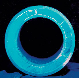 |
Fig. 1. A conventional cement on casing cracked after being subjected to high internal pressure, making it permeable to gas or water.
|
|
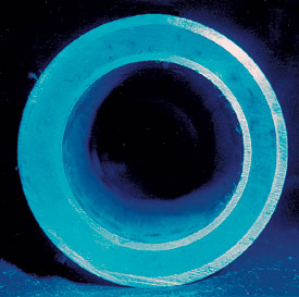 |
Fig. 2. Subjected to high internal pressure, this foamed cement on casing remained intact because of improved ductility.
|
|
In the study, 50 oil well cement slurries, ranging in density from 6 to 19 lb/gal, were examined in a 300°F environment. The researchers reported “no signs of matrix cracking, either radially or circumferential,” in foamed cement slurries in the 20-to-35-quality range.
Foamed cement is one of several solutions that can be used in combination to deal with the damage mechanism associated with formation compaction caused by reservoir depletion. The excellent displacement qualities of foamed cement, and the resulting bond, make it an excellent choice for primary cementing of production casing, especially where reservoir compaction or salt formation flow is a concern.10
Other foamed cement properties have been viewed with some concern by operators, although these characteristics can be considered advantages.
Strength. Foamed cement’s low compressive strength does not increase the risk for fracture initiation and propagation during hydraulic-fracturing treatments and casing-pressure testing, since these stresses are tensile in nature. The cement’s compressive strength is of minimal importance.11
Permeability. Table 1 presents test data that compare the permeability of foamed cement with that of conventional lightweight cement. In thousands of wells cemented with 20-to-35-quality, foamed cement systems, casing-sheath permeability to gas, water and oil has not been an issue or matter of concern to operators. Table 2 presents permeability and strength data for typical high-solids, non-foamed, lightweight cements.
| |
Table 1. Permeability and compressive strength of typical foamed cements1 |
|
| |
Cement
class |
Foam
quality,
% gas |
Density,
lb/gal |
Test
temper-
ature, °F |
Three-day
compressive
strength, psi |
Permeability
to water, md |
|
|
|
|
| |
C |
21.7 |
11.6 |
80 |
1,400 |
<0.001 |
|
| |
C |
25.8 |
11.0 |
80 |
1,150 |
<0.001 |
|
| |
C |
31.2 |
10.2 |
80 |
870 |
Not tested |
|
| |
C |
32.5 |
10.0 |
80 |
850 |
0.3 |
|
| |
H |
22.9 |
12.0 |
80 |
1,100 |
<0.001 |
|
| |
H |
33.1 |
10.4 |
80 |
600 |
<0.001 |
|
| |
Trinity Lite |
26.4 |
10.0 |
107 |
555 |
<0.001 |
|
| |
Trinity Lite |
26.4 |
10.0 |
143 |
1,025 |
0.067 |
|
| |
C |
28.8 |
10.0 |
107 |
575 |
<0.001 |
|
| |
C |
28.8 |
10.0 |
143 |
630 |
0.27 |
|
| |
C2 |
33.2 |
8.0 |
107 |
265 |
0.048 |
|
| |
C2 |
33.2 |
10.0 |
143 |
170 |
<0.001 |
|
| |
C2 |
22.7 |
10.0 |
107 |
1,425 |
<0.001 |
|
| |
C2 |
22.7 |
10.0 |
143 |
1,415 |
<0.001 |
|
| |
1Foamed cements of 20-to-35 quality, only, are recommended for use as oil- and gas-well cements. All results shown in this table are from foamed slurries within this quality range.
2Contains fly ash and amorphous silica as lightweight additives. |
|
|
| |
Table 2. Permeability and compressive strength of typical lightweight cements |
|
|
| |
Cement
class |
Lt. Wt.
Add. |
BHCT,
°F |
BHST,
°F |
Density,
(lb/gal) |
Comp.
Str., psi |
Permeability,
md |
|
|
|
|
| |
C |
Amorphous |
150 |
200 |
8.05 |
3,982 |
0.00147 |
|
| |
|
silica, glass |
|
|
|
|
|
|
| |
|
beads |
|
|
|
|
|
|
| |
C |
(Same) |
150 |
200 |
8.9 |
4,099 |
0.00154 |
|
| |
C |
(Same) |
150 |
200 |
10 |
4,772 |
0.0018 |
|
| |
C |
Amorphous |
90 |
120 |
8.04 |
2,740 |
Not tested1 |
|
| |
|
silica, |
|
|
|
|
|
|
| |
|
glass beads |
|
|
|
|
|
|
| |
C |
(Same) |
90 |
120 |
9 |
3,720 |
Not tested1 |
|
| |
C |
(Same) |
90 |
120 |
10 |
3,860 |
<0.001 |
|
| |
C |
Amorphous |
90 |
120 |
8.3 |
2,110 |
Not tested1 |
|
| |
|
silica, |
|
|
|
|
|
|
| |
|
glass beads |
|
|
|
|
|
|
| |
C |
(Same) |
90 |
120 |
8.9 |
2,850 |
<0.001 |
|
| |
C |
(Same) |
90 |
120 |
10 |
3,500 |
<0.001 |
|
| |
C |
Fine-grind |
90 |
90 |
8 |
2,170 |
Not tested1 |
|
| |
|
cement, |
|
|
|
|
|
|
| |
|
glass beads |
|
|
|
|
|
|
| |
C |
(Same) |
90 |
90 |
9 |
2,070 |
<0.001 |
|
| |
C |
(Same) |
90 |
90 |
10 |
3,770 |
<0.001 |
|
| |
|
|
|
|
|
|
|
|
| |
1 Sample broke in test fixture. |
|
|
Economy. Flexible cement can provide the ultimate resistance to stress-relaxation cycles compared to conventional cement, which can crack in two to 10 stress-relaxation cycles.7 Further, the initial investment in a flexible cement job is at least two orders of magnitude higher than a foamed cement job. Since a foamed cement system can tolerate hundreds of stress-relaxation cycles, foamed cement is often the most logical selection for a marginal or mature field. 
LITERATURE CITED
1 Ravi, K., M. Bosma and O. Gastebled, “Safe and economic gas wells through cement design for life of the well,” SPE paper 74700, presented at the SPE Gas Technology Symposium, Calgary, Alberta, Canada, April 30 – May 2, 2002.
2 Ravi, K., M. Bosma and O. Gastebled, “Improve the economics of oil and gas wells by reducing the risk of cement failure,” SPE paper 74497, presented at the IADC/SPE Drilling Conference, Dallas, Texas, Feb. 26 – 28, 2002.
3 Fleckenstein, W. W., A. W. Eustes III and M. G. Miller, “Burst-induced stresses in cemented wellbores,” SPE Drilling and Completion, June 2001.
4 Goodwin, K. J. and R. J. Crook, “Cement sheath stress failure,” SPE paper 20453, presented at the 66th Annual SPE Technical Conference and Exhibition, New Orleans, Sept. 23 – 26, 1990.
5 Onan, L., “High-temperature, fluid-induced casing collapse,” internal Halliburton laboratory report CCM-B008-94, Nov. 18, 1996.
6 Bosma, M., K. Ravi, W. van Driel and G. J. Schreppers, “Design approach to sealant selection for the life of the well,” SPE paper 56536, presented at the 74th SPE Annual Technical Conference and Exhibition, Houston, Oct. 3 – 6, 1999.
7 Benge, G. O., J. R. McDermott, J. C. Langlanais and J. E. Griffith, “Foamed cement job successful in deep HTHP offshore well,” Oil and Gas Journal, Mar. 11, 1996.
8 Kopp, K.; S. Reed, J. Foreman, B. Carty and J. Griffith, “Foamed cement vs. conventional cement for zonal isolation-case histories,” SPE paper 62895, presented at the 75th Annual Technical Conference and Exhibition, Dallas, Oct. 1 – 4, 2000.
9 Faul, R., B. R. Reddy, J. Griffith, R. Fitzgerald and B. Waugh, “Next-generation cementing systems to control shallow water flow,” OTC paper 11977, presented at the Offshore Technology Conference, Houston, May 1 – 4, 2000.
10 White, J., S. Moore and R. Faul, “Foaming cement as a deterrent to compaction damage in deepwater production,” SPE paper 59136, presented at the IADC/SPE Drilling Conference, New Orleans, Feb. 23 – 25, 2000.
11 Deeg, W., J. Griffith and R. Crook, “How foamed cement advantages extend to hydraulic fracturing operations,” World Oil, Nov. 1999.
THE AUTHORS
|
 |
Ron Crook is a senior technical advisor at the Halliburton Technology Center, Duncan, Oklahoma. There, he is responsible for disseminating information on zonal isolation subjects throughout the company. In his 30 years with Halliburton, Mr. Crook has been issued 13 patents, has six patents pending, and has published 36 technical papers and journal articles. He holds a BS degree in chemical engineering from Oklahoma State University and is a member of SPE and API. He chairs API Committee 10, Publications, and is a member of two more API committees (Cooperative Testing Group and Gas Migration Group).
|
 |
David Kulakofsky is the Halliburton champion for lightweight cementing solutions, working in Houston. He has more than 20 years of experience with cementing design in field operations in Africa, India and Texas, and at the Halliburton Technology Center in Duncan, Oklahoma. Mr. Kulakofsky attended Rensselaer Polytechnic Institute and holds a BS degree in chemical and ocean engineering from the University of Rhode Island.
|
 |
James Griffith is the business segment manager for cementing innovations at the Halliburton Technology Center in Duncan, Oklahoma. He is a registered professional engineer with more than 17 years of experience in production, drilling and reservoir simulation. Mr. Griffith has authored 51 technical papers and journal articles, and has co-patented 16 products in areas of cement-sheath integrity and evaluation, deepwater cementing and foamed cementing. He earned BS and MS degrees in petroleum from the University of Oklahoma, and he holds an MBA degree from Oklahoma City University.
|
| |
|
|

