Advances in fatigue design: Curvature index theory
Drilling ReportAdvances in fatigue design: Curvature Index theory and case studyHow drill string and trajectory designs can be optimized to significantly reduce fatigue damageJason Clark, Nicholas Reynolds and Sean Ellis, T H Hill Associates, Inc. ; John Stuart, PetroQuest Energy, Inc. Fatigue is the leading cause of drill string failures during rotary drilling. Complexity of the fatigue mechanism and inability to account for cumulative fatigue damage make absolute fatigue life prediction impractical. However, drill string and trajectory designs can be optimized to significantly reduce fatigue damage. This is accomplished by using fatigue life prediction models to analyze relative effects that different design options will have on fatigue life, and to quantify the advantage of one design over another. This article describes the application of a new technique to compare relative fatigue lives of drilling tubulars being rotated in curved wellbores. This unique methodology, called Curvature Index (CI) compares different designs for the combined fatigue effects of hole curvature, pipe size, weight, grade, class and axial tension in the tube. On a recent well in the US Gulf Coast region, PetroQuest Energy, Inc. experienced numerous drill string fatigue failures while drilling the 8-1/2 in. and upper portion of the 6-1/2-in. hole sections, and was wary of continued failures while drilling ahead. PetroQuest and T H Hill Associates, Inc., working together, identified the problem and altered drill string design and operating parameters to reduce the potential for fatigue damage. Subsequently, the well was successfully drilled to TD with no additional fatigue failures. CI was one of the key tools used for designing the drill string that successfully drilled the remainder of the well. INTRODUCTION Based on failure analyses conducted by T H Hill over the past two years, fatigue accounts for about two thirds of all drill string failures, as shown in Fig. 1.
Complexity of fatigue. The fatigue mechanism is affected by material properties, mud corrosivity, trajectory, rotary speed, loads and several other factors. This complexity, plus the lack of meaningful knowledge about the amount of prior fatigue damage, makes accurate, absolute fatigue life prediction practically impossible. Further, existing fatigue models rely on experimental data to calculate fatigue life, but this data is rarely available for drill string components. Relative fatigue life comparison. The factors above make fatigue lives determined by calculation so inaccurate that they are not useful for predicting absolute fatigue life in drill string components. However, results from these models are very useful for comparing the relative fatigue resistance of design alternatives when unknown factors are held constant and only known factors are varied. CURVATURE INDEX This is an analytical tool that uses the relative fatigue life comparison concept. It can be used to compare relative fatigue lives of a given drill string in various operating conditions, or of multiple drill strings under the same operating conditions, or both. CI is determined by first calculating stresses in the outer fiber of the tube due to bending and axial tension. This calculation is based on the work of Arthur Lubinski.1 The calculated axial and bending stresses are then input into the Forman Crack Growth Model2 to calculate fatigue life (in cycles to failure) of the tube body. Fatigue life is converted to CI using Equation 1. Thus, a lower CI represents a longer fatigue life. The purpose of Equation 1 is simply to reduce the numbers to more manageable sizes, and discourage misuse of the calculated fatigue life as an absolute value. CI values for two or more sets of conditions are quantitative measures of the relative rates of fatigue accumulation. The calculations hold constant those factors usually unknown to the designer, while varying those that the designer is likely to know. The ratio of one CI value to another represents the ratio of fatigue lives, other things equal. Applications of CI include comparing the effects on fatigue life of: 1) Dogleg severity; 2) Hanging load below a dogleg; and 3) Pipe size, weight, grade and class. CASE STUDY In 2003, during the drilling of an exploration well in the Gulf Coast region, five drill string fatigue failures occurred within a six-day period. At one point, a tube that was recently inspected washed out after drilling only 912 hr. All of the failures occurred in the same shallow depth interval. Investigation showed no metallurgical problems with the drill string and no apparent issue with the trajectory, as the MWD survey data (taken at 100-ft intervals) showed a dogleg severity less than 1°/100 ft over the interval of interest. However, because of the number of failures in the same location, the operator ran a gyro survey through the problem interval at 5-ft stations. This survey showed a dogleg of about 20°/100 ft in the interval where the failures were occurring. Fatigue was clearly the failure mechanism, and because of the probability of more failures, the economic feasibility of continued drilling was cast into doubt. Designing a new, fatigue-resistant drill string became the focus of the investigation. When attempting to mitigate fatigue damage, four main items should be addressed:
With the above factors in mind, the fatigue resistance of each of the six drill string configurations shown in Table 1 was evaluated. Designs 1 and 2 were those that suffered the fatigue failures. Designs 3, 4, 5 and 6 were new designs that were analyzed for possible use; Design 3 was ultimately selected.
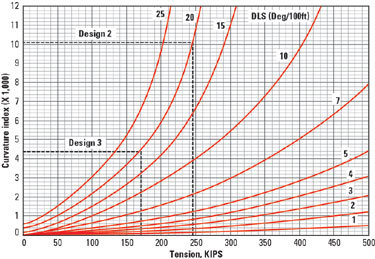
All analyses were performed assuming the 20°/100 ft dogleg was the primary cause of the fatigue failures. Since CI incorporates several of the factors that contribute to fatigue, it was used as the primary tool for choosing between design alternatives. Table 2 displays some design values for the two drill strings that sustained failures (Designs 1 and 2) and for the four alternatives being considered (Designs 3, 4, 5 and 6).
Design 3 was chosen because it has the lowest CI and, hence, the longest fatigue life. Compared to Designs 1 and 2, that failed repeatedly, expected life of alternative 3 is some 230% greater. Fig. 2 compares CIs of Designs 2 and 3. Equal CI values represent equivalent fatigue life, and the ratio of CIs quantitatively represents the ratio of expected fatigue lives.
In addition to redesigning the drill string, the operational parameters, drill string attributes and inspection protocol were addressed to further reduce the rate of fatigue damage accumulation, and help ensure the quality of pipe delivered. Operations. The following three operational effects were realized:
Drill string attributes. Internal plastic coating works as a barrier between corrosive mud and drill pipe ID. Stress relief features in HWDP eliminate unengaged thread roots (stress concentrations) and allow more flexibility within the connection. Both of these features were incorporated for pipe run in the new design. Other attributes. In many circumstances, Charpy V-notch impact test records are excellent tools for estimating a material’s ability to resist fatigue crack propagation. In addition, HWDP with a minimum yield strength of 100,000 psi, when compared to standard 55,000-psi HWDP, will operate at a lower percentage of its yield, given the same applied axial tension. This results in slightly better fatigue performance. Also, 100,000-psi HWDP will have been quenched and tempered rather than normalized. This will provide a more refined and uniform grain structure, which generally yields better material fracture toughness. In this case, however, neither test records nor high-strength HWDP were available in the short time at hand. Inspection program. DS-1* Category 3-5 inspection3 with a Magnetic Particle Inspection of the slip and upset area was selected for the HWDP. Case study summary. The remaining 2,000 ft to total depth was drilled with Design 3 over 17 days without another fatigue failure. This design, based on using CI as a comparative tool, was several times better with respect to fatigue, when compared with original designs that failed. The reduction in rotary speed further increased the drill string’s fatigue life. The additional steps of employing inspected pipe with internal plastic coating and stress relief features no doubt helped as well, though the exact amount cannot be quantified. CONCLUSIONS Because fatigue causes such a high proportion of drill string failures, there is drastic need for improvement in fatigue design methods. Curvature Index combined with other fatigue mitigation techniques can significantly improve ability to design a fatigue-resistant drill string. For designers wishing to use this tool, a full suite of curves similar to Fig. 2 will be available in DS-1* Third Edition, due for release late this year. Repetitive fatigue failures at the same depth indicate a trajectory problem. Such a problem may not show up with wide survey spacing.
|
|||||||||||||||||||||||||||||||||||||||||||||||||||||||||||||||||||||||||||||||||||||||||||||||||||||||||||||||||||||||||||||||||||||||||||||||||||||||||||||||||||||||||
- Applying ultra-deep LWD resistivity technology successfully in a SAGD operation (May 2019)
- Adoption of wireless intelligent completions advances (May 2019)
- Majors double down as takeaway crunch eases (April 2019)
- What’s new in well logging and formation evaluation (April 2019)
- Qualification of a 20,000-psi subsea BOP: A collaborative approach (February 2019)
- ConocoPhillips’ Greg Leveille sees rapid trajectory of technical advancement continuing (February 2019)

