Underbalanced Drilling
Field case history shows merit of UBD in northeastern Brazil
Four horizontal wells were successfully drilled underbalanced in a field with a shallow, unconsolidated reservoir. Additionally, a new, compact vertical gas-liquid separator tested well in its debut
H. Santos, Impact Engineering Solutions; and F. S. N. Rosa and J. C. Cunha, PhD, Petrobrás
Estreito field is in Brazil’s northeastern region and has its production zones depleted, Fig. 1. Discovered in 1982, it has more than 700 wells. Estreito field’s producing reservoir is very shallow, and the formation is very unconsolidated. This poses a special challenge to maintaining an underbalanced condition during drilling. Special care is required, not only during planning and execution of well operations. Four horizontal wells were planned and drilled underbalanced. In these wells, a compact, vertical gas-liquid separator was successfully tested with an automated control system and data acquisition system developed by Petrobrás. A skimmer was used for drilling solids, fluid-oil separation.
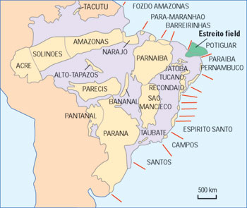 |
Fig. 1. Estreito field lies in Brazil’s northeastern region.
|
|
OVERVIEW
Estreito field produces heavy oil with high viscosity (>1,000 Cp). Average output from vertical wells is between 3 and 4 m3/day (19 and 25 bopd). Horizontal wells produce 10 to 15 m3/day (63 to 94 bopd).
The wells’ low productivity increases lifting costs, requiring such special recovery methods as cyclic and continuous steam injection to increase output. Use of the UBD technique at Estreito tested this method’s technical and economical feasibility to increase oil production. This four-well campaign offered the opportunity to field-test several new pieces of equipment and operational procedures that would be used offshore later, where wells with aerated fluid would be drilled for the first time from a drilling vessel.
The objective of the four wells described here was to drain an area under the Açu River. The horizontal section extension was approximately 150 m (492 ft), drilled with an 8-1/2-in. bit. Original pressure of this unconsolidated sandstone reservoir was 20 kg/cm2. The estimated depletion is about 3 kg/cm2 in the area under the river – still not heavily depleted. Formation fluid is basically oil with no associated gas.
A 13-3/8-in. conductor was set at 40 m (131 ft), and the intermediate 9-5/8-in. casing was set at 90° inside the reservoir. Finally, the 7-in., slotted production casing was set in the horizontal section, Fig. 2. This casing was cemented using a stage tool inside the 9-5/8-in. casing. An external casing packer was used to avoid overpressuring the formation during cementing.
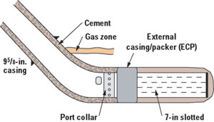 |
Fig. 2. This wellbore plan is typical of the horizontal wells drilled in the Estreito UBD horizontal project.
|
|
DRILLING TECHNIQUE
The 8-1/2-in. horizontal section was drilled underbalanced using a two-phase fluid comprised of water and xantham gum to keep it slightly viscosified. This fluid sustained the iron sponge used to avoid any H2S problems (which did not occur). Anti-corrosion measures were also applied, and pH was kept above 10.5. The gas was nitrogen pumped from trucks.
Liquid and gas rates were planned to assure an equivalent circulating density lower than the reservoir pressure, estimated at 7.4 ppg. Because the reservoir is unconsolidated, wellbore stability studies were conducted to determine the collapse pressure. Best estimation was that this collapse pressure would be equivalent to 6.5 ppg, even though several uncertainties can affect the value’s accuracy.
Two static and one transient simulator were used to simulate well hydraulics, and liquid and gas rates. The flowrates found in the simulators were around 240 gpm of liquid (with an 8.5-ppg, liquid-phase density) and 350,000 cfgd. In the field, liquid rates of 150 to 200 gpm and gas rates of 500,000 to 700,000 cfd were used. The difference between predicted and actual flowrates was due to pressure losses at the surface, greater than originally estimated. Liquid phase density was also higher than the one used in the simulations.
The transient simulator was used to estimate the effect of pipe connections (adding new pipe joints to the drillstring as drilling went deeper) on BHP. This simulation showed that it was going to be very difficult to keep BHP between the limits defined by the collapse pressure (219 psi) and the reservoir pressure (250 psi). What happened was that when reinitiating circulation, a liquid slug formed during connection of new pipe that would provoke an increase in BHP. Conversely, when circulation was stopped, BHP would gradually drop, due to the absence of friction loss. This would cause BHP to go below collapse pressure, which consequently, would cause wellbore instability.
Theoretically, the solution for this problem was to use a nitrogen pre-charge before connecting new pipe. In this case, liquid injection would be interrupted 90 sec before the gas, and the emergency shutdown valve on the flowline would be closed during connection, keeping the well pressurized. The goal of the pre-charge is to add more gas to the liquid that will remain at the bottom of the well due to gas segregation. By closing the valve, this segregation will be minimized, keeping BHP above collapse pressure. Connection time is also important – for simulation purposes, it was estimated at 4 min.
An electromagnetic MWD was used to control the well’s direction. A gamma ray tool and an annular BHP sensor were connected to the MWD. Both data sets were recorded in real time at a distance of 14 m (46 ft) from the bit. These data were recorded every 96 sec.
SEPARATION/PROCESS SYSTEM
While liquid nitrogen was pumped from trucks, gasified and then injected through the standpipe, the liquid phase was pumped by mud pumps. The mixture of both phases occurred in a Y connection at ground level before going up to the standpipe.
On the return, a rotating control head (Williams 9000 model) was used above the regular BOP stack, allowing return flow to go to the separation system. This rotating head allowed a maximum 1,000-psi static pressure and 500 psi when rotating the string at a maximum 100 rpm.
After the rotating head, the flow passed through a choke manifold specifically designed and built for underbalanced operation. Before the choke, there was a normally closed safety valve with a remote pneumatic actuator. For this operation, the system was changed to normally open. The 3,000-psi working pressure choke had three streams – one full, and two with a variable choke pneumatically controlled. A sample catcher was located after the choke that was also specially designed and built, with screens inside cylindrical reservoirs where the sample was retained when the flow was forced to pass through them, Fig. 3.
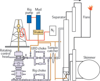 |
Fig. 3. Included in this surface equipment layout is a specially designed and built sample catcher, inserted after the choke.
|
|
Just after the sample catcher, the gas-liquid-solids mixture entered the Petrobrás vertical, two-phase separator. This cylindrical separator is 6-m high, has a 20-in. diameter and is built with two concentric pipes. The mixture enters the separator tangentially at its top. From there, the flow moves downward, passing through the annular of the two concentric pipes in a helical trajectory.
In this movement, the gas is separated, goes inside the inner pipe to the top of the separator and then proceeds to a secondary separator that retains any liquid still present in the mixture. After that, the gas goes to the burner. Conversely, the liquid-solids mixture goes to the separator bottom and from there to the skimmer. The separator works with a liquid seal (to avoid gas going to the skimmer with the liquids-solids mixture). Pneumatic valves automatically control the liquid seal’s level.
The skimmer receiving the liquids-solids (drilling fluid, oil and cuttings) mixture has three tanks able to collectively hold 280 bbl. The first tank holds cuttings, and the other two separate oil from the drilling fluid.
DATA ACQUISITION SYSTEM
A dedicated, fully automated control system was developed and used during operations to control all parameters, as well as opening and closing control valves. A typical screen from the data acquisition system is shown in Fig. 4. In this case, the screen shows a zero liquid level inside the separator. This was before the operation. All equipment and valves are displayed in a manner that makes it very simple for the operator to control the whole process from the control cabin. Another monitor was remotely located at the driller’s cabin that allowed the driller and rig floor personnel to follow the operation.
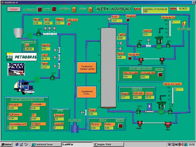 |
Fig. 4. In this sample screen from the data acquisition system, a zero liquid level inside the separator is visible before operations began.
|
|
Meanwhile, when the data is shown in real time, it is also being recorded for future analysis. An example of some data plotted against time is shown in Fig. 5. Contrary to other standard UBD operations, this data set is more complete, including separator levels, pressures and actuation of the control valves. Also the system was linked to the MWD/PWD (pressure while drilling) tool. The list of recorded parameters includes:
- Injection liquid and gas flow rates
- Injection temperature and pressure
- Rotating control head pressure
- Separator liquid level
- Liquid and gas outlet flowrates
- Separator work pressure
- Outlet liquid density
- Control valves’ percentage openings
- Bottomhole pressure
- Well depth.
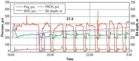 |
Fig. 5. Contrary to some UBD operations, this pressure vs. time data set recorded in real time is quite complete, showing separator levels, pressures and control valve actuation.
|
|
Therefore, full control of the operation was in place at all times, even including observation of the influence of surface equipment on BHP. In many instances, when this is not possible, BHP might be above the desired value due to mishandling of chokes or valves at the surface. With this automated control system, some operational practices were changed to avoid overbalanced conditions. Since the separator and control system were new, some of the practices implemented were different from current ones, improving the whole operation significantly.
Alarms were in place for liquid injection, separator liquid level and separator work pressure. This allowed a much safer operation.
OPERATIONS
To save stand-by time for equipment and personnel dedicated to underbalanced operations, it was decided to batch drill the four wells. Therefore, the horizontal sections were drilled only after the four wells had been drilled and cemented to the intermediate casing string at a 90° inclination.
Attempts to avoid an overbalanced condition after the connection, by using a gas pre-charge after shutting in the liquid, were not practical. This was due to difficulties in coordinating the mud pumps and extra time required for gas injection. This was especially difficult due to the wells’ shallow depths. Conversely, closure of the emergency shutdown valve at the surface, to avoid reduction of BHP below the collapse pressure, caused a sudden pressure increase and big slugs that impaired separator performance.
During the first well, actual collapse pressure was lower than predicted. Consequently, after connection, BHP was allowed to go to a lower value, just by shutting in the injection without any special procedure. Accordingly, the pressure increase after the connection was not as high as the simulator predicted. Even though an underbalanced condition was not always guaranteed, only during small periods of time did BHP reach values slightly above the estimated reservoir pressure.
Due to a problem on the nitrogen injection flowrate, which indicated a wrong value, the first well was drilled overbalanced during a majority of the horizontal section’s initial portion. It was first supposed that the PWD was registering a wrong value, but, after everything was checked, it was concluded that the nitrogen flowmeter was wrong. Because oil production was being achieved – and half of the horizontal section had already been drilled – it was decided to keep BHP at the same level to avoid affecting formation stability. The chart of BHP, and estimated collapse and reservoir pressures, can be seen in Fig. 6. In the remaining wells, this problem was solved, and the underbalanced condition was more stable.
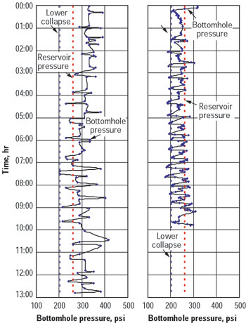 |
Fig. 6. In these charts of BHP and collapse and reservoir pressures, the contrast is evident between the first well (left) that experienced nitrogen injection problems and had to be drilled mostly overbalanced, and the other wells, where underbalanced conditions were more stable.
|
|
Another interesting point to mention was a sudden, unexpected huge slug of nitrogen during the last third of one of the wells. A detailed investigation was conducted on all the measured and recorded values, and no apparent reason was found. One possible explanation might be gas accumulation on the upper side of the horizontal section. At a certain point, the gas slug suddenly migrates to the surface. This phenomenon deserves further investigation, as it can cause serious problems during underbalanced operations.
Total drilling time for each well ranged from 8 to 9 hr., except for the first well, which took 13 hr. In the same field, four other horizontal conventional wells were drilled recently, and the average drilling time for each horizontal section was 13 hr.
Oil production achieved during drilling averaged 150 bpd. Due to the oil’s relatively high viscosity, skimmer efficiency was poor. Heating up the oil or adding some chemicals could have helped the oil/water separation, but these measures were not attempted. Oil content in the drilling fluid increased to 10% at the end of the well from the initial 0% value.
The well was planned for UBD and completion. Accordingly, a great effort was made to change the original well design, casing and cementing practices, and casing cleaning. After the slotted casing was cemented, from the intermediate casing shoe to the surface, the remaining cement plug and the slotted casing were washed and cleaned with nitrogen to avoid overpressuring the formation. Significant oil production during this period was observed.
At this time, it is not yet possible to check well production performance in comparison to other wells drilled conventionally. The idea is to measure not only oil output but also productivity improvement, to verify the benefits of drilling wells underbalanced. Higher fluid levels were observed inside wells after they were drilled underbalanced, so it can be concluded that formation damage was lower than usual. Quantitative measurements will be conducted as soon as production reaches a steady state.
CONCLUSIONS
This project was a successful venture by an integrated team comprised of personnel from different areas – drilling, reservoir engineering, geology, research and service companies. Integration of the team from the initial stages of planning, through training and field operation, was a key factor in the project’s success.
After this first underbalanced campaign, one can conclude that UBD is a feasible technique, even in an unconsolidated formation. To cope with this more aggressive drilling practice, wellbore stability analysis should incorporate new failure criteria and methods. Current wellbore stability simulators tend to be very conservative.
Both hydraulic simulators used – the steady state and the transient models – were accurate enough compared to field data, and were very important during the well planning stage. The automated data and control acquisition system is essential for having a safe, successful UBD operation. The new compact vertical separation was approved, and this same concept was used later offshore during a field test of drilling with lightweight fluids.
Preliminary results indicate an increase in productivity from the wells drilled underbalanced, compared with conventional wells. 
ACKNOWLEDGMENTS
The authors thank Petrobrás for permission to publish this article. The following individuals contributed greatly to the project: Ivo Martins, Jose Feliciano, Jose Arias, Sara Shayegy, Paulo Roberto Silva, Carlos Fernando Fonseca (in memorium), José Luis Falcão, Gladston Paolucci, Ricardo Allan, Ricardo Eugenio, Angela Vargas and Roberto Rodrigano.
Bibliography
Borba, G. L., A. L. Paula, E. C. Almeida and E. E. Brito, “Horizontal drilling in shallow sandstones, unconsolidated and with heavy oil,” 1st Petrobrás Well Engineering Seminar, Rio de Janeiro, Brazil, Nov. 25 – 29, 1996 (in Portuguese).
Cunha. J. C., and F.S.N. Rosa, “Underbalanced drilling technique to improve drilling performance – a practical example,” Rio Oil & Gas Conference, Rio de Janeiro, Brazil, Oct. 5 – 8, 1998 (in Portuguese).
Falcão, J. L. and C. F. Fonseca, “Underbalanced horizontal drilling: A field study of wellbore stability in Brazil,” SPE Asia Pacific Oil and Gas Conference and Exhibition, Brisbane, Australia, Oct. 16 – 18, 2000.
Nakagawa, E., H. Santos, and J. C. Cunha, “Application of aerated fluid drilling in deep water,” World Oil, June 1999.
Nakagawa, E., H. Santos, and J. C. Cunha, “JIP’s work brightens outlook for UBD in deep waters,” American Oil & Gas Reporter, April 1999.
THE AUTHORS
|
| |
Hélio Santos earned BS and MSC degrees in civil engineering from PUC-RJ in 1982 and 1989, and a PhD in geological engineering in 1997 from the University of Oklahoma. He joined Impact Engineering Solutions in 2001 as vice president, technology, responsible for development of a new drilling system and introduction of a new class of drilling fluid. Mr. Santos is also in charge of new technologies with potential to make a step change in drilling. Before joining Impact, he worked at Petrobrás for 18 years, including three years offshore as a drilling engineer before moving to the Petrobrás Research Center. He has been involved in several projects related to optimized drilling and special drilling techniques.
|
|
Fábio Severo N. Rosa holds a BS in chemical engineering and joined Petrobrás in 1985. His experience includes drilling supervision and well design. He has been involved in drilling wells underbalanced and near-balanced, using air, foam and aerated fluids. Mr. Rosa has worked in the design phase, development of new equipment and operating procedures, and has been directly involved in drilling operations and managing contracts for new equipment needed. He is a technical consultant for drilling at Marlim Sul field, in Brazil’s Campos basin.
|
| |
J. C. Cunha is a senior technical advisor for Petrobrás. After joining the company in 1979, he has worked in a number of onshore and offshore drilling projects in Brazil. His experience includes stints for Petrobrás International in various South America countries, the Gulf of Mexico, Africa and the Caribbean. Originally a civil engineer from Juiz de Fora University, Brazil, Dr. Cunha holds an MSc from Ouro Preto University, Brazil, and a PhD from Tulsa University, both in petroleum engineering. His main areas of interest are related to drillstring mechanics, wellbore stability, horizontal and extended reach wells, underbalanced drilling and risk analysis. He has written more than 40 technical papers.
|
|

