Intelligent Well Completions
Tiltmeter mapping for long-term reservoir monitoring
How surface tiltmeter mapping has proven effective in tracking fluid movement through a reservoir. Case histories demonstrate positive results
Kevin Fisher and Larry Griffin, Pinnacle Technologies
Numerous technologies are used to instrument intelligent wells in oil/gas fields, providing measurements of fluid movement within a reservoir. 4-D seismic is used to monitor changes in fluid saturation with time, and some wellbores are permanently instrumented with sensors that provide direct surface read-out of downhole pressure, temperature, production and fluid cuts. Microseismic and tiltmapping technologies have proven very useful in field flood, waste disposal and geotechnical applications. This article will focus on long-term surface tiltmeter monitoring technology and how it has been used to optimize injection projects. Case histories from California fields and disposal injection projects demonstrate positive results.
In conclusion, several technologies have been successfully utilized for reservoir monitoring. Surface tiltmeter mapping has proven extremely robust and effective and can be used to track fluid movement through a reservoir, resulting in significant savings to operators by preventing problems before they occur. Future reservoir monitoring arrays will integrate tilt and microseismic sensors, allowing even better real-time measurement of reservoir response to fluid injection and withdrawal.
INTRODUCTION
Tiltmeter mapping technology has been applied to monitor a wide range of injection and production activities. These projects include: conventional hydraulic fracture treatments,1-12 waterfloods,3, 13, 14 EOR (steam injection),15 and injection disposal.16-18 Tiltmeter arrays are ideally suited for long-term monitoring of subsidence or dilation caused by production or injection (including waste disposal). The benefits of monitoring long-term injection projects include: 1) providing a real-time alarm system for detecting out-of-zone injection; 2) performing direct measurements critical for understanding and optimizing the injection process and contributing another key parameter (deformation) for reservoir simulation; and 3) helping expedite regulatory approval for many injection projects by providing the security of a direct measurement of fluid movement.
Pinnacle began tilt mapping in the oil, gas and geomechanical industries worldwide in 1991. More than 6,000 tiltmeter mapping operations have been performed, and this technology has expanded to include long-term injection monitoring. Automated software now performs much of the analysis/monitoring functions, and results can be made available daily on a secure web site. The accuracy of monitoring techniques and rapid-result availability allows clients to visually understand and optimize the injection process, while remaining within the allowable limits of vertical and lateral fracture growth. These intelligent reservoir services have proven accurate, and are designed to remain in place for years of continuous service.
Benefits of directly measuring surface deformation are numerous, especially when problems can be identified early and remedial measures taken prior to expensive failures. The monitoring system provides a real-time alarm capable of continuous deformation surveillance over an entire field. Out-of-zone fracture growth (either vertical or lateral) can be quickly identified so that corrective measures may be immediately taken and reservoir integrity maintained. The information obtained is key to understanding the injection/disposal process and how it can change with rate, time and volume of injected fluid or slurry. Obtaining direct measurements of fluid placement with long-term deformation monitoring can also aid in gaining and expediting regulatory approval for many projects.
PRINCIPLES OF TILTMETER MAPPING
Surface tiltmeter fracture mapping is a unique fracture diagnostic technology that provides a direct measurement of fracture: orientation (azimuth and dip), volume, complexity, and approximate location based on deformation of the earth’s surface. In addition to monitoring fracture growth, Pinnacle’s tiltmeter arrays are ideally suited to the long-term measurement of subsidence or dilation caused by production or injection. Tiltmeter-based fracture mapping relies on devices and principles that are simple and intuitive.
The tiltmeter instrument. A tiltmeter sensor is, in essence, an extremely sensitive carpenter’s bubble level, Fig. 1. A quartz tube is filled with a conductive fluid and a small bubble of gas. As the instrument tilts, the gas bubble moves to maintain its alignment with the local gravity vector. The area of the electrodes in contact with the fluid determines how much electrical current flows between an excitation electrode and several pickup electrodes. The difference in electrical current flowing between the two electrodes is amplified, digitized and used to determine how far the sensor has tilted.
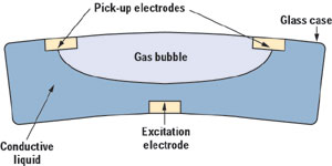 |
Fig. 1. Tilt sensor bubble.
|
|
Each tiltmeter has two sensors to determine tilt in both horizontal axes. Tilts on these two axes are used to determine magnitude and direction of tilt at each individual instrument in an array. Pinnacle’s tiltmeters can measure changes in tilt magnitude of about 1 nanoradian (1 billionth of a radian, or approximately 5.7x10⁻⁸ degrees). To put this in perspective, this is the amount of tilt that would occur if one were to take an infinitely rigid beam, spanning the distance from New York to San Francisco, and raise one end by only 1/4-inch!
How surface tilt mapping works. A surface tiltmeter array designed to fully characterize injection-induced deformation typically consists of 30 or more instruments positioned radially around the injection well(s).
The tilt sites are self-contained, with communication to the sites achieved by high-gain radio telemetry links, Fig.2. A central computer periodically polls each tiltmeter or automatically downloads tilt data collected during a predetermined cycle period (typically 24 hours or less). Once the information is collected, it is automatically transmitted to a central Pinnacle computer center for analysis and automated generation of graphical results. Results are uploaded to a secure client web site and can be accessed by clients anywhere in the world in near real-time.
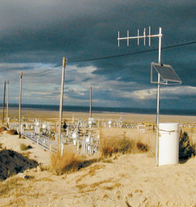 |
Fig. 2. Typical tiltmeter site outfitted with radio telemetry for long-term fracture/deformation monitoring.
|
|
Surface-tiltmeter reservoir monitoring involves measuring the production and/or injection-induced tilt at many points above the reservoir, then solving the inverse problem to determine the fracture parameters and delta-pore-pressure-induced motion that produced the observed deformation field. Magnitudes of the induced surface deformations are quite small and require highly sensitive devices that measure deformation gradient (or tilt). The spacing and number of tiltmeters depend on injection depth and desired resolution.
In some fields, one or more high-precision GPS sites are also added to the array. Addition of GPS insures that surface elevation changes – which are calculated from the gradient measurements – do not deviate from actual surface motion, even over many years. Combining the extreme precision of tilt measurements with the tremendous long-term stability of GPS yields a system with the advantages of both.
Induced tilt is measured throughout the course of injection to measure fluid placement location and orientation. In rare cases, fractures may initiate in one plane and then twist into another orientation or, more commonly, initiate secondary fracture growth in another plane at some time during an injection operation. Monitoring injection with time also allows shifts in fracture center location, both lateral and vertical, to be determined; it is this aspect of deformation mapping that makes it valuable for detecting out of zone growth.
Almost every EOR/IOR injection project initiates hydraulic fractures. Careful analysis of falloff data will show that almost any project that is successful at putting fluid in the ground without loss of injectivity over time must be operating at parting pressure. The induced deformation field at the surface is primarily a function of created-fracture size and shape, Fig. 3, although deformation due to increases in pore pressure can be significant in some reservoirs.
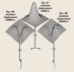 |
Fig. 3. Surface deformation for induced fractures of different orientations.
|
|
The induced deformation field is almost completely independent of reservoir mechanical properties and in situ stress state. For example, a north-south trending vertical injection-induced fracture yields the same surface deformation pattern whether the fracture is in low modulus diatomite, extremely hard carbonate, or even unconsolidated sandstone.
The simplicity of the concept allows robust and unambiguous determination of primary fracture parameters such as fracture azimuth and dip, created fracture volume, depth to fracture center and fracture offset due to asymmetric growth, all from an array placed near the surface of the earth.
Monitoring upward fracture growth. Detection/measurement of upward fracture growth is valuable in injection disposal projects and in cases where vertical-injection fluid movement into nearby areas is undesirable, and while there is still time to cease or alter an injection strategy. Surface tiltmeters are effective for detecting relatively large depth shifts in fracture location. In situations where precise identification of upward fracture growth is critical, downhole tiltmeters are often utilized to measure changes in fracture height. Situations where long-term installation of downhole tiltmeters is not practical or possible may include presence of very high downhole temperature, tubular restrictions, lack of a nearby offset well and/or need to monitor a very large area.
APPLYING LONG-TERM RESERVOIR MONITORING
Several ongoing projects utilize tiltmeter-based, long-term reservoir monitoring systems; some of these intelligent fields have been monitored for more than three years. The primary function of these arrays has been to quickly detect out-of-zone fracture growth at the injection well(s) before it becomes a severe problem- – where mechanical integrity of wellbores may be compromised, or where injected fluid may approach an interval where it is not permitted.
Tiltmeter arrays are ideally suited for long-term measurement of subsidence or dilation caused by production or injection activities. Fluid movement and pressure changes can often be inferred from the deformation, contributing to overall optimization of the injection process in waterflood and EOR projects. Long-term reservoir monitoring with surface tiltmeters has proven extremely valuable for maintaining reservoir and wellbore integrity and for optimizing production.
Presently, several long-term surface tiltmeter projects are ongoing in the Southern San Joaquin Valley, California. These arrays have allowed clients to monitor entire fields with ongoing injection operations. The ability to identify origin/growth of shallow fractures has been critical for maintaining reservoir and wellbore integrity. Large areas have been continually monitored to identify and help remediate propagation of shallow fractures that typically result in casing and cement failures. Direct hydraulic communication between adjacent injection wells is often identified from fractures that are alternately inflated and deflated. In addition, Pinnacle has monitored subsidence to aid in calibrating injection and production volumes to maintain pore pressure balance in the reservoir.
Production/injection-induced deformation patterns can be incorporated into a reservoir simulation model. With addition of downhole tilt arrays, these deformation measurements can become very precise in locating specific layer(s) that are moving. The deformation pattern becomes another constraint to be used as an input history-matching parameter (pressure, production and injection rates are some others) in coupled reservoir and geomechanical simulators. The addition of measured deformation patterns significantly improves predictive capabilities of the simulators and adds to the ultimate recovery in oil and gas reservoirs.
For real-time internet data access, after considerable experience with permanent tilt monitoring arrays, refinement of the system has been made so that most functions are automated and results are made available each day, only hours after data collection. Continuous monitoring results are posted to Pinnacle’s secure client web site. Rapid turnaround between data acquisition, processing and visualization allows engineers to respond quickly to subsurface deformation events within their intelligent field.
With addition of the optional GPS component, this system is now capable of measuring cumulative surface deformation with sub-centimeter accuracy over any time scale and minute-by-minute resolution, if desired. Remote access is available through any web browser. The graphical input format allows clients to request special analyses or reports automatically.
CASE HISTORIES
SPE paper 62577, Precise tiltmeter subsidence monitoring enhances reservoir management,15 documents long-term deformation monitoring of waterflood and steam injection projects in the San Joaquin basin of California.
South Belridge. Waterflooding in South Belridge field was designed to increase production, as well as to mitigate compaction and subsidence. The extremely low permeability of this diatomite reservoir resulted in extreme pressure gradients between the injection and production wells. Previous tiltmeter work3 determined that this pressure gradient alters the stress field and causes the hydraulic fractures on new wells to reorient adversely to the designed waterflood orientation pattern, and it may cause the injection patterns to short circuit, i.e., undesired direct communication from injector to producer.
To prevent this on new infill wells, a successful strategy of first completing all wells before beginning production has been employed. The same tiltmeter array was then used to monitor the fracs and measure/control the resulting subsidence. It has also been found that, by correlating subsidence with injection/production activities, damage due to buckling of casing can be minimized.
Cymric/McKittrick. Ongoing surface tilt monitoring of cyclic steam injection in Cymric/McKittrick field has aided in understanding and improving steaming process effectiveness, but it has also proven extremely valuable for preventing casing failures where steam is being injected out of zone, Fig. 4. Using this same technique, areas with excessive subsidence are also identified, and injection/withdrawal rates are modified to avoid casing buckling and damage. SPE 62577 also documents a case of identifying a lateral shift of a fracture away from the injection interval.15 Video examples of long-term reservoir monitoring can be viewed at www.pinntech.com.
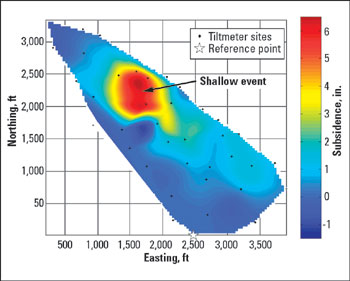 |
Fig. 4. Example of a detected shallow fracture event in a cyclic steam injection project, Cymric/McKittrick field, California.
|
|
Mapping disposal injections. Surface tilt mapping has been applied to waste disposal projects including the Mounds Drill Cutting Disposal Experiment16 and slurry fracture injection (SFI) in Canada.17, 18
For the Mounds project, surface and downhole tiltmeter arrays (as well as microseismic monitoring tools) were used to perform real-time monitoring of fractures induced by drill cuttings injection. Tilt mapping successfully identified location (azimuth and dimensions) of numerous hydraulic fractures from multiple injections in the Wilcox Sand and Atoka Shale. Core-through results later confirmed the tilt mapping accuracy. The Mounds project demonstrated the creation of a disposal domain in hard rock sand and shale intervals. This same behavior has been documented in Canada for Slurry Fracture Injection (SFI) projects in soft unconsolidated, high permeability formations.17, 18 
LITERATURE CITED
1 Wright, C. A., et al., “Reorientation of propped refracture treatments in the Lost Hills field,” paper SPE 27896, presented at the 1994 Western Regional Meeting, Long Beach, CA, March 23 – 25.
2 Wright, C. A. and R. A. Conant, “Hydraulic fracture orientation and production/injection induced reservoir stress changes in diatomite waterfloods,” paper SPE 29625, presented at the 1995 Western Regional Meeting, Bakersfield, CA, May 8 – 10.
3 Wright, C.A. and R.A. Conant, “Hydraulic fracture reorientation in primary and secondary recovery from low-permeability reservoirs,” paper SPE 30484, presented at the 1995 Annual Technical Conference and Exhibition, Dallas, TX, Oct. 22 – 25.
4 Warpinski, N. R., “Evaluation of a downhole tiltmeter array for monitoring hydraulic fractures,” Int. J. Rock Mech. & Min., 34:3-4, Paper No. 329, 1997.
5 Wright, C. A., et al., “Horizontal hydraulic fractures: Oddball occurrences or practical engineering concern?” paper SPE 38324, presented at the 1997 Western Regional Meeting, Long Beach, CA, June 25 – 27.
6 Wright, C. A., et al, “Wellbore-to-fracture communication problems pose challenges in California diatomite horizontal wells,” paper SPE 38632, presented at the 1997 Annual Technical Conference and Exhibition, San Antonio, TX, Oct. 5 – 8.
7 Wright, C. A., “Tiltmeter fracture mapping: From the surface and now downhole,” Hart’s Petroleum Engineer International, January 1998.
8 Wright, C. A., et al., “Surface tiltmeter mapping reaches new depths-10,000 feet, and beyond?” paper SPE 39919, presented at the 1998 Rocky Mountain Regional/Low Permeability Reservoirs Symposium, Denver, CO, April 5 – 8.
9 Wright, C. A., et al., “Downhole tiltmeter fracture mapping: Finally measuring hydraulic fracture dimensions”, paper SPE 46194, presented at the 1998 Western Regional Meeting, Bakersfield, CA, May 10-13.
10 “Downhole tiltmeter fracture mapping: A new tool for directly measuring hydraulic fracture dimensions,” paper SPE 49193, presented at the 1998 Annual Technical Conference and Exhibition, New Orleans, LA, Sept. 27 – 30.
11 Wright, C. A., et al., “Understanding hydraulic fracture growth: Tricky but not hopeless,” paper SPE 56724, presented at the 1999 Annual Technical Conference and Exhibition, Houston, TX, Oct. 3 – 6, 1999.
12 Emanuele, M. A., et al., “A case history: Completion and stimulation of horizontal wells with multiple transverse hydraulic fractures in the Lost Hills diatomite,” paper SPE 46193, presented at the 1998 Western Regional Meeting, Bakersfield, CA, May 10 – 13.
13 Griffin, L.G., et al., “Identification and implications of induced hydraulic fractures in waterfloods: Case history HGEU,” SPE 59525, presented at the 2000 SPE Permian Basin Oil and Gas Recovery Conference, Midland, TX, March 21 – 23.
14 Mayerhofer, M., et al., “Tiltmeter hydraulic fracture mapping in the North Robertson field, West Texas,” SPE 59715 presented at the 2000 SPE Permian Basin Oil and Gas Recovery Conference, Midland, March 21 – 23
15 Davis, E., C. Wright, C., and S. Demetrius, “Precise tiltmeter subsidence monitoring enhances reservoir management,” paper SPE 62577, presented at the 2000 Western Regional Meeting, Long Beach,, CA, June 19 – 23.
16 Griffin, L.G., et al., “Surface and downhole tiltmeter mapping: An effective tool for monitoring downhole drill cuttings disposal,” paper SPE 63032, presented at the 2000 Annual Technical Conference and Exhibition, Dallas, TX, October 1 – 4.
17 Sipple-Srinivasa, et al., “Field experiences with oilfield waste disposal through slurry fracture injection,” paper SPE 38254, presented at the 1997 Western Regional Meeting, Long Beach, CA, June 23 – 27.
18 Bruno, M. S., et al., “Economic disposal of solid oil field waste through slurry fracture injection,” paper SPE 29646, presented at the 1995 Western Regional Meeting, Bakersfield, CA, March 8 – 10.
THE AUTHORS
|
 |
Kevin Fisher, VP of business development, Pinnacle Technologies, holds a BS in physics from Cameron University. He worked for Halliburton for 15 years as logging engineer, supervisor, log analyst, US sales manager and global marketing manager. Prior to joining Pinnacle in 2000, he was with ProTechnics as director of sales and marketing for eight years and was awarded several patents related to spectral gamma ray and gravel pack density logging. He is involved in integrating fracturing diagnostic measurements with real-time fracture modeling, and has written numerous technical papers and articles on well logging and fracture diagnostics. He can be reached at kevin.fisher@pinntech.com
|
 |
Larry Griffin, Pinnacle Technologies’ diagnostic services manager, graduated from Texas Tech University with a BS in PE. He is responsible for delivery of fracture mapping and reservoir monitoring services, including tilt and microseismic technologies. Prior to this, as an engineer for Pinnacle, he consulted on a wide range of stimulation, diagnostic and reservoir monitoring projects worldwide. Before joining Pinnacle in 1998, he worked for ARCO in West Texas and Alaska for 17 years in reservoir, operations and completions engineering. Just prior to leaving ARCO, he was responsible for stimulation activity in the Greater Kuparuk Area of Alaska. He can be reached at larry.griffin@pinntech.com
|
| |
|
|

