Deepwater Drilling Technology
Benefits of dual-gradient methods for drilling upper hole sections
Proven in a recent offshore field test, subsea mudlift drilling can now be applied to significantly reduce total well costs, starting with more efficient top-hole drilling
P. R. (Hari) Hariharan and Bob Judge, SMDC, a Hydril subsidiary
The Subsea MudLift Drilling-Joint Industry Project (SMD-JIP) concluded after a successful field test in the Gulf of Mexico in late 2001. Since then, Subsea MudLift Drilling Co., or SMDC, a subsidiary of Hydril, was created by agreement of the JIP participants to market dual-gradient-drilling (DGD) technology to the industry. SMDC is poised to bring DGD to the market in the form of a Top-Hole Drilling (THD)* system, providing many of the benefits of DGD, as well as other unique advantages.
This arrangement applies DGD technology to the upper hole section of a well, where maximum benefits are derived due to the small margin between pore and fracture pressures in the GOM. This article summarizes results of the dual-gradient field test. Also presented are reasons and justification for concentrating efforts to bring DGD technology to market through a THD system, rather than a complete system that would drill the entire well using dual-gradient equipment.
FIELD TEST RESULTS
SMD-JIP prototype testing of the Subsea MudLift Pump (MLP) was conducted on a well drilled in about 1,000-ft water in Block GC 136 in 2001. After setting 20-in. casing, mud in the riser was completely replaced with seawater, and 2,700 ft of 17-1/2-in. hole was drilled in a complete dual-gradient mode. While drilling, the mud and all drilled solids were pumped from seafloor to surface through a separate 6-in. return line. After drilling a 17-1/2-in. hole to TD, 13-3/8-in. casing was run and cemented, with all operations carried out in dual-gradient mode.
During successful completion of the field test, all critical drilling and well-control procedures were tested and verified. There were a total 128 original test objectives established for the MudLift Pump, as well as the operational / well-control procedures. These objectives were divided into three categories based on level of criticality, as discussed here.
Category I. This category was the most critical, with 15 distinct objectives. These were formulated so that some of the most important questions regarding feasibility of sustained and continuous dual-gradient drilling operations in the field were tested. The objectives are summarized here, i.e., to verify ability of: 1) the MLP to maintain a constant / stable inlet pressure during startup, pumping operations and shut-down; 2) the MLP to regulate wellbore annular pressure at the mudline as required; and 3) the SMD system to detect a kick and perform basic well-control operations utilizing the SMD system and procedures.
All of these objectives were met with success and the required interval was drilled in dual gradient without any equipment or procedural problems.
Category II. This category had 21 objectives, and generally involved more detailed tests for sustained dual-gradient operations. They involved slightly less critical issues, but addressed important routine operations such as:
- Ability of MLP, to control system pressures in constant-pressure mode.
- Testing the solids processing unit (SPU).
- Verification of tripping and drill-ahead procedures in dual gradient.
- Ability of SMD system to apply an increased pressure margin.
- Verification of casing running/ cementing operations.
Category III. There were 92 separate items grouped in this category. They were primarily related to operational and running procedures of the SMD system, rather than verification of the DGD concept, which was covered in Categories I and II. Nevertheless, these items had to be tested and separately verified to consider the field trial a success. Several items in this category were related to the running procedure of the SMD system and working of the seawater power system. Some of the main objectives in this category were:
- Tripping operations of the SMD system
- Management of the dual-trip-tank system, and
- Verification of the ability of the SMD system to quickly respond to rate changes made to mud pumps by the driller; and verify functioning of drillstring valve (DSV), subsea rotating diverter (SRD), and solids processing unit (SPU).
In all, 90% of the 128 objectives were tested, with the SMD equipment and procedures passing all of the tests. The remaining objectives were not tested due to budget constraints, but these were primarily duplicate testing opportunities for tests already completed.
In summary, drilling of the test well verified that the SMD system could be integrated with a rig, and a real well could be drilled in dual-gradient mode. The testing program verified that all generated solids could be brought to surface through a separate line without any plugging of the subsea pump or flowlines. All system components functioned in the required fashion without major problems, once drilling began. All procedures related to drilling, tripping, casing and cementing operations were proven to work without any problems. The ability to control pressure and carry out a well-control operation with the SMD system was also clearly established.
Although no major flaws were discovered, there were several "learnings." Some of these were related to equipment design and improvements of the support system and infrastructure. Others were related to simplification and better operational procedures.
The only unknown regarding the future of DGD technology is whether there is sufficient interest and demand for drilling wells utilizing the technology. The many benefits of DGD operations have been a subject of much discussion through several papers and articles over the last few years. 1-5
HESITATION TO ADOPT NEW TECHNOLOGY
Despite benefits of DGD, as touted over the last few years through several publications and articles, apprehension associated with adopting new technology, especially in the oil industry, can be discouraging for innovators / developers of new ideas / equipment. The primary risk centers on costs resulting from equipment failure subsea.
Another concern has been the need for committing a large amount of capital to deploy a system. Additionally, this level of commitment carries over to a commitment to use a particular drilling vessel for a long term. These concerns stem from an assumption that the DGD system would be utilized for the entire well.
There has been further debate in recent literature whether dual-gradient technology has shifted from being an “enabling” technology to merely an “enhancing” or “cost saving” technology.6 Certainly, there is not significant exploration in the water depths were DGD is truly “enabling” from a reservoir standpoint. Additionally, development of other enabling technologies, such as expandable tubulars, limit looking at the enabling aspects of DGD to justify its use. Therefore, the case must be made – at least in the short term – that DGD must be justified as a cost-savings technology.
While it is true that developments have been made in parallel technologies such as expandable tubulars, there has not been an “enabler” so far for eliminating riserless drilling in the upper or top-hole sections without mud returns to the rig, i.e., “pump and dump.” The SMD technology alone could contribute to eliminating this process. In ultra-deep waters, where top-hole formations are insufficiently competent to withstand conventional-drilling pressures, DGD could be the only answer.
From a risk mitigation standpoint, SMDC has studied whether there is a possibility of deploying DGD technology separately from the critical path of expensive offshore drilling operations conducted from a 4th- or 5th-generation rig using single-gradient or conventional drilling operations in deep waters.
This article examines the option of utilizing SMD for drilling the top sections of a well, primarily for 30-in. surface and 20-in. conductor phases alone. Given the fact that the industry should be more comfortable trying out new technologies in low-risk environments, with no commitment for long-term contracts, the best means of making the technology available should be through deployment of the DGD system adapted to drill the top hole alone.
For a production or development scenario involving drilling a well cluster, the top holes could be batch drilled and cased using the DGD system. Later, a separate rig could drill out and complete the wells in single-gradient. Using such a configuration, there are ample opportunities to save well-construction costs. Another attractive feature is the opportunity to circulate mud back to the surface rig, virtually eliminating the dumping of mud and cuttings while drilling riserless.
TOP HOLE DRILLING: IMMEDIATE ADVANTAGES
In view of the discussion above, the best means of attacking market resistance to new technology should be from a risk-mitigation standpoint. This could occur if the top portions of the well – primarily surface and conductor-casing intervals, generally the 30-in. and 26-in. hole – are drilled in dual gradient, using the SMD system with a rig that is either 3rd or 4th generation, with capabilities to bring mud returns to the rig. This rig would be cheaper than a 4th- or 5th-generation rig currently utilized in similar locations.
It is envisaged that this “spud rig” only carries the SMD system, which would be deployed to the seafloor utilizing a “mini riser” comprising two conduits of 5-in. or 6-5/8-in. drillpipe size. These would carry power fluid and mud returns, and act as the running string for the subsea mud pump, Figs 1 and 2.
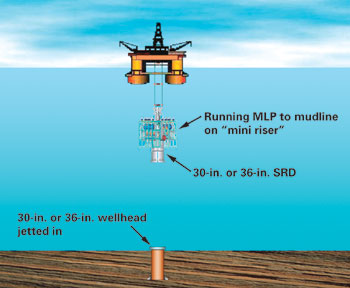 |
Fig. 1. Schematic illustrating running of MudLift pump package from Top-Hole Drilling (THD) rig.
|
|
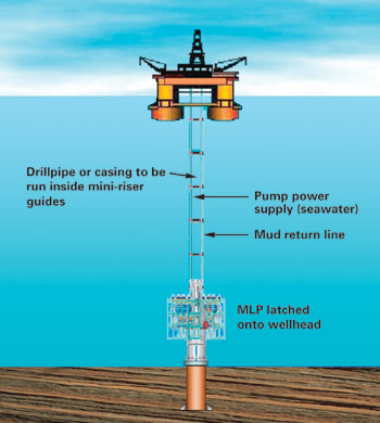 |
Fig. 2. MudLift package of THD system latched onto subsea wellhead.
|
|
Several advantages of THD are listed as follows, and although some of these have been discussed elsewhere, 7 they are restated here: 1) elimination of “pump and dump”; 2) management of shallow hazards; 3) extending conductor casing reach; 4) decreasing cycle time between wells due to modified casing programs; 5) fewer number of wells due to larger completions; and 6) risk mitigation. Two of the above points are discussed below.
Risk mitigation. Perhaps the greatest advantage obtained from using a THD rig is risk mitigation. All risks associated with drilling the upper-hole sections have been transferred to a lower-generation, less-costly rig. In deep water, where shallow-water flows and equipment downtime will increase overall well cost, it is sensible to transfer risks to a less-expensive rig.
In the case of novel technology such as the DGD system, consequences of an equipment failure that necessitates tripping the system from the seabed, and repairing and returning it to the seafloor could take up to a week. It would be very advantageous, especially to an early adopter of the new technology, to have such an event occur while using the less expensive “spud rig” rather than a full-capability 4th- or 5th-generation vessel.
No more “pump and dump.” Substantial advantages could be obtained with elimination of this process. Since the mud, along with all drilled cuttings can now be returned to surface, opportunities exist to use specialty muds. While drilling large-diameter holes in the soft/ unconsolidated clays in the upper sections, hole quality by way of borehole stability and shale inhibition is of great concern.
COST ANALYSIS
Two cost-analysis cases from actual deepwater-well information were developed and examined for possible savings that could be obtained using a dual-gradient system for drilling the upper hole portions. For these wells, it was assumed that, after the upper-hole sections were drilled, the THD rig moved away. A follow-on rig positioned itself on location, re-entered the well and completed it in single gradient.
For both cases, the key issue centered on setting the marine conductor and 20-in. surface casing deeper. In both cases, this resulted in the saving of one intermediate casing string below, and all associated costs.
Assumptions made in performing the analysis were very conservative and include: 1) mobilization / demobilization assumed for both the conventional single-gradient operation and the THD operation; 2) 0% failure probability assumed for all single-gradient operations; 3) 35% failure probability assumed for the subsea dual-gradient-pumping system; and 4) no complications such as shallow-flow incidents, lost circulation, stuck pipe, etc. The resulting cost-analysis cases are:
Case 1. This case consisted of a well drilled in the GOM in 2,500-ft water to 22,500 ft. The well took 25 days to drill at a cost of $45 MM. The well had 20-in. casing as a marine conductor and 16-in. as the surface casing, Fig. 3. This well was modeled by “drilling the well on paper” and took almost the same number of days.
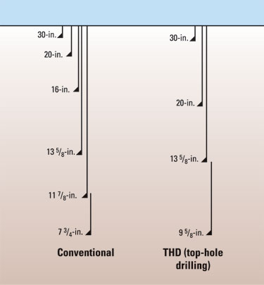 |
Fig. 3. Comparison of casing configuration of conventional and THD well in 2,500-ft water. Note that the 20 in. is set deeper, resulting in saving at least one casing string (16 in.).
|
|
A probabilistic analysis run on the case showed drilling cost to vary from $40.7 MM (at 10% probability, P10) to $41.9 MM (P90). The same well was modeled for THD operations using two rigs and two mob-demobs. The resulting THD-drilled well cost was $36.8 MM (P10) to $38.2 MM (P90), providing a savings based on Monte Carlo probabilistic simulation varying from 11.4% (P10) to 6.5% (P90).
Case 2. This was a well drilled in the GOM in >7,000-ft water, to about 18,000 ft. It took about 60 days to reach target depth, at a cost of about $22 MM, which included weather downtime, Fig. 4. The well was “drilled on paper” in single gradient without weather downtime, and a probabilistic risk analysis showed cost of the modeled well to vary from $21.4 MM (P10) to $21.6 MM (P90). Assumptions were similar to those assumed in the previous case. The well was “drilled” using THD, and the analysis indicated cost varied from $16.1 MM (P10) to $16.8 MM (P90). This is a savings range of 29.2% (P10) to 32.1% (P90).
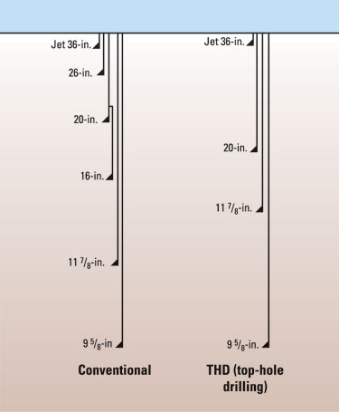 |
Fig. 4. Comparison of casing configuration of conventional well with that of a THD well in >7,000-ft water. Setting the 20 in. deeper eliminates both the 26-in. and 16-in. strings.
|
|
Other potential options/benefits. Another area where possibilities exist for saving further cost is completing the well in single gradient utilizing a smaller rig after the upper sections have been drilled with the THD system. This is based on the fact that the conductor casing – usually 20 in. or 16 in. – is set deeper, and savings of at least one casing string is obtained. With such a possibility, an opportunity is created to drill the subsequent hole sections utilizing a smaller size subsea BOP (probably 13-5/8-in.) with a slim riser.
DRIVING THE MARINE CONDUCTOR DEEPER
One item that must be addressed when trying to set the surface casing deeper is that the marine conductor must also be set deeper. This requirement stems from the fact that when geological events such as shallow water or gas are encountered, the pressure would be contained by raising wellbore annular pressure using the subsea mud pump. This requires the marine conductor to have a higher level of shoe integrity than is required conventionally.
The present depths to which the 30-in. or 36-in. marine conductor is jetted in the GOM are 250 to 300 ft BML. To guarantee shoe integrity, the conductor would have to be set much deeper than the present depths. Many times, the 30-in. is run and cemented, which then proves to be costly. Other available options to drive the conductor deeper could include technologies such as casing drilling and pile driving, as discussed below.
Casing drilling. This is a fast-evolving technology, with the potential to reduce drilling costs.8 With casing drilling, the marine conductor could be set deeper, being drilled and cemented in place all in one trip (or at the most, two trips). Casing drilling is presently being conducted with up to 13-3/8-in.; extending to larger sizes, i.e., 30 and 20 in., would have to be established. Further, it has to be established that the process also makes sound economic sense, compared to setting an intermediate conductor, i.e., 26 in.
Pile driving. The original impetus to drive 20-in. conductor piles came from the need to control shallow-water flows. Recent literature discusses the possibility of driving conductors deeper, utilizing a technique called bottom or toe hammering, as opposed to the conventional top hammering.9 This technique could perhaps also be utilized to drive the 30-in. conductor pile to deeper depths, whereby the resulting shoe would have sufficient integrity to withstand back pressures imposed by the subsea mud pump to control and manage shallow-water flow.
The low-pressure wellhead housing should also be part of the pile that is driven, ensuring that the casing is driven to predetermined depths. The subsea pump could then be run and latched to the wellhead housing and the hole (26 or 24 in.) drilled in dual-gradient mode with complete mud returns to the rig. It should then be possible to drill to deeper depths, e.g. to 6,000 ft BML, enabling deeper setting of the 20-in. conductor. Every scenario would have to be considered on a well-to-well basis, including the economics of such an undertaking.
SUMMARY/CONCLUSIONS
The discussions presented in this article point to these conclusions: 1) a good way to introduce new technology such as dual-gradient drilling is through a lower-cost drilling rig deployed for drilling the upper hole sections only; 2) the prime advantage obtained by this method of introducing DGD is minimizing the risk of deploying the subsea pump equipment by minimizing the cost of failure, i.e., equipment retrieval and repair, and rig down time; and 3) risk is also mitigated by transferring the risk of encountering and managing shallow-flow incidents to a lower-cost rig.
Further, all such attempts to try out new technology should be preceded and substantiated by sound probabilistic economic analysis. And novel techniques such as casing drilling or pile driving need to be investigated to set the marine conductor to deeper depths to improve the integrity of the shoe. 
LITERATURE CITED
1 Smith, K.L., et al., “Subsea MudLift Drilling JIP: Achieving dual gradient technology,” Deepwater Technology, August 1999.
2 Smith, K.L, et al., “Dual gradient drilling nearly ready for field test,” World Oil, October 2000.
3 Schumacher, J.P., et al., “Subsea MudLift Drilling: Planning and preparation for the first subsea field test of a full-scale dual gradient system at Green Canyon 136, Gulf of Mexico,” paper SPE 71358, presented at the 2001 SPE Annual Technical Conference and Exhibition, New Orleans, Louisiana, Sept.-Oct. 2001.
4 Eggemeyer, J.C., et al., “Subsea MudLift Drilling: Design and implementation of a dual gradient drilling system,” paper SPE 71359, presented at the 2001 SPE Annual Technical Conference and Exhibition, New Orleans, Louisiana, Sept.-Oct 2001.
5 SubSea MudLift Drilling: Joint Industry Project Phase III final report, December 2001.
6 Frazelle, A.E. and R.R. Brainard, “What has happened to the industry's commercialization of dual gradient technology,” 14th Annual Deep Offshore Technology Conference, New Orleans, Louisiana, Nov. 2002.
7 Judge, B. and H. Hariharan, “Exploring the benefits of DGD technology in top hole drilling,” Offshore Engineer, July 2002.
8 Shepard, S.F., R.H. Reiley and T.M. Warren, “Casing drilling: An emerging technology,” SPE 67731, presented at the SPE/IADC Conference, Amsterdam, February 2001.
9 Choe, J. and H.C. Juvkam-Wold, “Unconventional method of conductor installation to solve shallow water flow problems,” paper SPE 38625, presented at the SPE Annual Technical Conference and Exhibition, San Antonio, Texas, October 1997.
THE AUTHORS
|
 |
P.R. (Hari) Hariharan is Manager of Drilling Engineering for Subsea MudLift Drilling Co., LLC. His responsibilities include dual-gradient drilling engineering and well-control issues. He has been with SMDC since 2001; prior to that with the Subsea MudLift Drilling JIP from 1999-2001. He has eight years’ field drilling experience with a major national oil company and three years drilling research experience, including ARCO as drilling research engineer. He holds a BSME from the University of Calicut (India), an MS (petroleum) from the University of Tulsa, and a PhD (materials science and mineral eng.) from the University of California, Berkeley. He is a member of SPE and ASME.
|
 |
Bob Judge is Director of Engineering for Subsea MudLift Drilling Co., LLC, a division of Hydril, responsible for equipment design and technical sales support. He has been with SMDC since 2001, working since 1998 with the Subsea MudLift Drilling JIP. He has over 12 years' oilfield equipment design experience. He holds a BSME from Texas A&M University, an MS from George Washington University, and he is a member of SPE.
|
| |
|
|

