 Technology from Europe Technology from Europe
EC technology round-up
Jonathan Shackleton, The Robert Gordon University, Aberdeen
Oil and gas will continue to provide more than half of Europe’s energy requirements well into this century. However, to remain competitive, it is important that the industry continues to invest in new technology that extends the producing life of existing fields and new marginal fields.
Described herein are five technologies funded by the European Commission’s (EC) ENERGIE program that are helping the oil business to stay profitable in maturing fields: 1) an advanced method for predicting flow paths; 2) new drilling turbines that improve efficiency; 3) well-stream monitoring for improved safety; 4) integrity monitoring of flexible risers and pipelines; and 5) an innovative compact separator.
An advanced method for predicting flow paths. Two principal aims of the FRACARES project, led by Hellenic Petroleum S.A. of Greece, were prediction of flow and determination of preferred flow pathways through a shallow onshore and fractured reservoir. Two associated aims were to identify the principal shortcomings of existing methodologies for analysis and modeling of fractured reservoirs and to establish means for resolving these problems.
The project was carried out in the Abadia Valley near Torres Verdas in central Portugal. The area contains a non-economic hydrocarbon reservoir, at a depth of more than 150 m, which is characterized by shallow-to-open marine Jurassic limestones within a faulted anticlinal structure, Fig. 1.
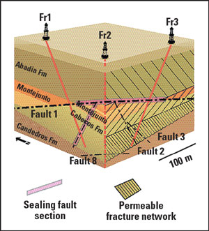 |
Fig. 1. Conceptual geological model of Abadia test field.
|
|
Such fractured carbonate reservoirs, containing oil and sometimes gas, often occur at shallow depths and close to outcrops of oil-bearing reservoir rock. They provide the ideal situation for demonstrating and testing the capabilities of integrated methods and technologies for the modeling and development of deeper reservoirs.
The Abadia Valley reservoir contains somewhat heavy oil (and some gas) that flows on testing and typically ranges from 15° to 25° API, due mainly to biodegradation and water percolation. There is no well-defined oil-water contact, but the reservoir is characterized by an oil-saturated fault system that taps downward into the underlying source rocks of the Cabacos marly limestone.
The project highlighted several significant fractured reservoir features and methods used in their analysis and modeling. With specific regard to flow characteristics of the Abadia reservoir, the project concluded that:
- Hydrocarbons generated in the source rock have migrated into the reservoir rock.
- There exists, within the reservoir, various compartments with discrete hydraulic properties.
- Fractures and faults within the source rock are not all equally conductive or well connected.
- Intrinsic permeability of the matrix rock (primary porosity) is essentially zero.
A model has been developed in which porosity comprises fractures and faults that define heterogeneous pathways for fluid flow. The project partners included GEUS (Denmark), IGM (Portugal) and the Fault Analysis Group (Ireland).
New drilling turbines improve exploration efficiency. Drilling applications are becoming more complex and costly. Consequently, new technological developments with improved methods and equipment that reduce costs are important, particularly in the current business climate. In a project undertaken by German company TIEBO, new turbine technology has been developed – a short gear-reduced turbine for steerable and hot-hole drilling applications. This new tool will be a valuable addition to high-standard, positive-displacement motors and turbines.
Rock bits have bit speeds of about 300 – 1,000 rpm (depending on hole size) allowing drilling with low weight-on-bit, which is particularly beneficial for horizontal drilling. Sliding operations become complicated as longer lateral sections with related torque and drag problems often make it difficult to control inclination and direction during the drilling process; and high weight-on-bit is difficult to achieve. Rotating the drillstring as long as possible has many advantages.
The integrated gear-reduced turbine has two main components: the turbine section and the bearing section (BS), Fig. 2. The turbine includes: up to 120 turbine blades (rotor/stator); radial bearings; and a pressure-compensation unit, for pressure equalizing between the oil against the mud system. The BS contains the axial and radial bearings and the lower seal assembly, with an option for a stabilizer.
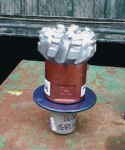 |
Fig. 2. 6-1/8-in. PDC bit with integrated gear reduced turbine and bearing section.
|
|
A titanium shaft connects both sections. Due to a multi-row planetary gear, it is possible to optimize turbine configurations for each application and to transfer high torques. The 120 blades can be modified with different characteristics based on job requirements. The technology has been field-tested and further development is taking place to improve drilling costs for TIEBO’s clients.
Well-stream monitoring becomes easier and safer. To manage field facilities wisely and maximize recovery, oilfield operators must know the flowrates of well-stream components. Their measurement is a difficult operation because oilfield production comprises a mixture of oil and gas, and usually water as well.
The conventional approach was based on periodic tests, involving separation of well-stream components in a test separator, followed by independent flowrate measurements of oil, gas and water. This project aimed to demonstrate the feasibility of continuous flowrate measurements using a combination of microwaves and ultrasounds.
Microwaves are already used to measure water volumetric fractions of a well stream. The main innovation of the project was to extend the technique to the measurement of hydrocarbon fractions (oil and gas).
The prototype was installed in Trecate field, Italy, in 1998 and tested during two months after an additional calibration, Fig 3. All site logistics (piping for connections, electrical supply, operator cabinet, etc.) and manpower (technical assistance, independent measurement, laboratory tests, etc.) were provided by Agip and Geoservices (France), with help from IFP (France) personnel to operate the flowmeter.
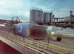 |
Fig. 3. The multiphase meter during tests.
|
|
The demonstration test saw no problems. A large amount of data was collected, corresponding to a wide operating domain. This was made possible by co-operation of the field operators who, on request, varied the combinations of well-stream flow in the meter to vary the operating conditions.
The test confirmed the ability of the meter to operate in an industrial environment. The test covered flowrates ranging from 3 – 35 m3/hr for liquids and 10 – 50 m3/hr for gas. The flow velocity corresponding to these flowrates were 0.2 – 2.0 m/s and 1 – 5m/s, respectively. In this domain, good accuracy (2 – 5%) and repeatability of the measures (below 0.6%) were obtained.
Geoservices is now developing the technology to replace mobile test separators. This decision was taken with the objective of offering better quality of services to oil operators. The company is developing an industrial meter that incorporates the knowledge acquired during the demonstration.
Integrity monitoring for flexible risers and pipelines. Inspection and assessment of flexible risers or pipelines on offshore facilities is required to satisfy both regulatory and safety requirements. Typically, this is done at a basic level because of a lack of assessment methods and inspection techniques suited to these complex components.
Recognizing this, the oil and gas industry has developed API Spec 17J, which sets minimum standards for design, specification, manufacture and testing of flexible pipe. A recommended practice was also prepared giving guidelines based on current best practices. The guideline, Guidelines for integrity monitoring of unbonded flexible pipes, emphasizes the need to collect data during the life of a pipeline/riser asset and the means to store and analyze the data.
FLEXSENS, developed by UK-based BHR Group, together with CorrOcean (UK) and MCS Int’l. (Ireland), aims to provide this through development of an intelligent Integrity Management System for flexibles. The aim of the FLEXSENS project was to demonstrate that key assessment and inspection technologies can be integrated such that pipeline designers and operators can make informed decisions on the maintenance and inspection requirements for their flexible assets – especially risers.
To do this, the project brought together the most up-to-date developments in sensing of flexible pipe with the best knowledge of design, failure-mode assessment and integrity management strategy for flexible-pipe systems. The complete system was then evaluated under a number of simulated riser fault conditions to demonstrate the potential of an integrated inspection and assessment system to pipeline operators, as well as identify problems and issues that might affect implementation of the technology by industry.
The FLEXSENS approach looks at the life cycle of the asset, including design, operation (and changing operating conditions), maintenance, inspection and decommissioning. It allows an operator to develop strategies – such as what to inspect, and how often – for individual assets and to re-assess these as inspection results or asset operations change. The modular nature of FLEXSENS inspection equipment will ultimately address a wide range of riser performance parameters.
The system is based on two essential components: 1) software that is a knowledge-based integrity-assessment design tool, used to determine and adapt integrity monitoring strategies; and 2) a pig-mounted inspection tool that uses smart sensors to measure changes in key pipeline characteristics.
The system’s benefits include:
- Making API guidelines easy to use and interpret
- Making best use of the judgments of technical specialists
- Determining the level of inspection needed at any given time
- Allowing operators to anticipate potential failures and take appropriate remedial action
- Ability to update management strategy based on monitored results
- Transparent technical audit trial.
The techniques are provided as a service through CorrOcean and MCS. The next phase of the development is to increase the functionality of the inspection system and validate the software over a wider range of operating scenarios. A major requirement will be to demonstrate the system under field conditions for which support is required from pipeline operators.
Compact separator proves its worth. Compact separators are highly desired by the oil and gas industry because they offer added benefits compared with conventional gravity separators. These benefits include: compactness, low fluid inventory, ability to operate at high pressure conditions such as at wellhead, insensitive to the motion of floating platforms/vessels, no moving parts, ease of operation and low maintenance.
A compact separator named I-SEP has been developed by UK-based CALTEC, the oil and gas division of BHR Group Ltd., Fig 4. Following its initial development, the laboratory trials demonstrated its robustness and potential for a variety of separation duties. This work was followed by design and manufacture of a full-scale high pressure unit and offshore field trials, supported by the EC.
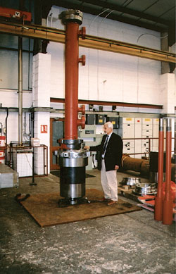 |
Fig. 4. Actual I-SEP device with integral knock-out vessel.
|
|
I-SEP is a patented system comprising a compact dual involute and a specially designed separation chamber. The function of the first involute is to generate spin and high-g forces as fluids pass through it. The high-g forces help the droplets of each phase to coalesce as they enter and pass through the small separation chamber. Within this part of the unit, the denser fluids gather close to the wall of the separation chamber, while the lighter phase is collected in the center core. The separated denser phase is then captured by the second involute, while the lighter phase is collected by a vortex finder.
The involute and the separation chamber are made of modularized sections bolted together for ease of assembly and change-out. The entire unit is then housed in a containment vessel. The phases involved in separation could be gas-liquid, gas-solids, liquid-solids, oil-water, or a mixture of these phases.
There are basic subtle differences between I-SEP and conventional hydrocyclones. Although both function on the basis of generating high “g” forces to effect separation, I-SEP is more tolerant to flow fluctuations compared to conventional hydrocyclones. I-SEP applications include: gas – liquid separation; knock-out liquid from wet gas; solid separation from gas or liquid phases; dust separation; and partial oil – water separation.
The unit can be designed for onshore, offshore and subsea applications. A miniaturized version has also been designed for downhole application. Potential field applications include:
- Underbalanced drilling
- High pressure, wellhead applications
- Well testing
- Sand separation at wellhead
- Multiphase metering
- Debottlenecking upstream of existing gravity separators
- Liquid re-circulation for multiphase pumps.
The system can be designed to different scales to suit each application and the range of flow conditions which it has to handle. In some applications where high flowrates are involved or a turn-down ratio in excess of 5 to 1 is desired, more than one unit may be used operating in parallel. 
For further information on these projects, email: j.shackleton@rgu.ac.uk.
|

