Nov. 2002 Vol. 223 No. 11
Feature Article
|
What’s New in Production
EOR by electro-acoustic reservoir stimulation: A new approach
How applying electrical current and mechanical vibrations into the reservoir improves hydrocarbon flow into the wellbore
Olav Ellingsen, Eureka Oil ASA, Norway
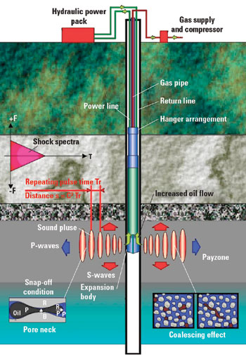
The following discussion explains and illustrates the technology of introducing alternating current, plus vibration created by a downhole “hammer” to increase the mobility of crude within the reservoir surrounding the wellbore. Following the technical description of the process, results of field tests in Brazil, Texas and heavy oil in Venezuela are presented.
The industry has, for decades, put a tremendous effort into developing means to improve production and recovery rate from land- and offshore-based oil reservoirs due to the simple fact that most of the oil is left in the reservoir when the field is abandoned. As oil is the world’s most important commodity, any contribution in harvesting more of this valuable resource is welcome. To this end, Eureka Oil ASA, a Norwegian company, is dedicated to developing an EOR technology invented by engineer Olav Ellingsen in 1986.
How It Works
The technology, named the Eureka Enhanced Oil Recovery Principle (EEOR) is an EOR method specially designed for land-based oil fields. The principle is based on electrical and sonic stimulation of the oil-bearing strata to increase the oil flow. This is accomplished by introducing special vibrations into the strata, which are as identical as possible to the natural rock matrix frequency, and/or fluids.
The vibrations give rise to several effects in the fluids and remaining gases in the strata. They decrease the cohesive and adhesive bonding, as well as a substantial part of the capillary forces, thereby allowing hydrocarbons to flow more easily within the formation.
Those vibrations that propagate into the reservoir as elastic waves will change the contact angle between the rock formation and the fluids, thereby reducing the hydraulic coefficient of friction. This allows a freer flow toward the wells, where velocity increases and creates a greater pressure drop around the well. The elastic waves give rise to an oscillating force in the strata, which results in different accelerations because of different fluid densities. The fluids will “rub” against each other due to different accelerations that create frictional heat which, in turn, reduces their surface tensions.
The vibrations will also release trapped gas, contributing to a substantial gas lift of the oil. Further, the oscillating force creates an oscillating sound pressure that also contributes to oil flow.
Heat is supplied to the reservoir to maintain and, at the same time, increase pressure conditions in the well area. The heat is supplied both as frictional heat from vibration, and as alternating current into the wells. The electrical transmission capabilities always present in an oil field allow AC to flow between wells to make the reservoir function in a manner similar to an electrode furnace, because of resistance heating.
The heating may cause a partial evaporation of the lightest hydrocarbon fraction. Further, the alternating current causes ions in the fluids to oscillate and, thereby, creates capillary waves on fluid interfaces, thus reducing surface tensions – a phenomenon named “The in situ electrified surfactant effect (IESE). ” Heat created by electrical stimulation and vibration reduces the fluids’ viscosity. The effect of these two stimuli are shown in Fig. 1.
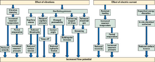 |
| Fig. 1. Increased flow-potential effects from vibration and electrical current. |
|
Electrical Stimulation
Various patents and solutions exist for use of electricity to heat oil-bearing formations. These methods are classified according to the dominant mechanism of thermal dissipation in the process. Frequency dictates how the electrical energy is converted to heat. Dielectric heating prevails at high frequency, as the dipoles formed by oil molecules tend to align themselves with the electrical field. Alternating this field induces a rotation of the molecules, with a velocity proportional to the alternating frequency. This molecular movement can be intense enough to produce considerable heat. A popular application of this process is in microwave ovens.
Another possibility is inducing heat where alternating electric current flows through a set of conductors. This induces a magnetic field in the medium. The magnetic field variation, in turn, induces a secondary current, which creates heat. This work is confined to the resistive heating process, which is the major mechanism when DC or low-frequency (up to 300 Hz) AC is used.
Energy input for each well depends on oil flow and bottom-hole temperature. This means that, for a particular electrode (casing) temperature, the greater the oil production, the greater the energy input possible because the oil produced drains away the increased heat at the well area.
In the EEOR process, low-frequency AC at 100 to 500 V is applied, depending on the resistance in the reservoir. The application of low-frequency electromagnetism (passing electric current directly through the formation) requires a conductive medium. When the formation water meets this requirement, the electric current will flow by ionic conduction, and care must be taken for temperature around the electricity injection wells not to exceed that of the water’s evaporation point. If this occurs, there will be a cut in the current and, then, it will be necessary to raise the voltage level to re-establish the circuit.
Applying Ohm’s law (resistive heat) to that of a radial and homogeneous system results in power dissipation expressed as:
| P(r) |
= |
2pd h
(DVe)2ln2(r/rw)/ln3(re/rw) |
| where: |
|
|
| P(r) |
= |
Dissipated power between well and reservoir volume at distance r from well; |
| d |
= |
Reservoir electric conductivity; |
| DVe |
= |
Drop in voltage between well and outer radius re (drainage radius, normally half the space between wells); |
| h |
= |
Formation thickness; |
| rw |
= |
Well casing diameter. |
Temperature increase at the well area is due to current flow from one well to the other. Because of resistance in the strata, the energy will be delivered at any place by the formula Px = RxI2, where Rx is electrical resistance at a distance x from the well. During the research period, immediate increased oil recovery was observed using electricity and vibrations, before a thermal effect was expected.
Ions at the fluid boundaries can be polymerized to a thickness of several molecules, and this is one of the effects that creates surface tension in a fluid. By changing polarity of the AC, the ions will oscillate at the same frequency as the current and thus, reduce surface tension – a phenomenon which is well known in the industry in electrostatic coalescers.
Arrangement
Electrical stimulation of the well can be arranged in different ways depending on actual well configuration. The energy is delivered from a thyristor-regulated power controller with a complete set of instrumentation to monitor current, voltage and energy delivered over each phase, in addition to temperature at the pay. Power to the wellheads is delivered by cables normally buried 30 cm in the ground. Cables at the wellhead are connected to the power-carrying cable down the well: 1) by insulated casings stripped at the payzone – cables are directly connected to the casing at the wellhead; or 2) by underreaming the existing casing above the payzone – current is delivered either by a downhole cable to the casing at the payzone or via tubing when using insulated centralizers.
In any of these arrangements, electrical safety is maintained by normal protection of any current-carrying parts. Each site is designed individually and an installation can comprise newly-drilled, underreamed and existing wells used as “antennas.” A typical arrangement is shown in Fig. 2.
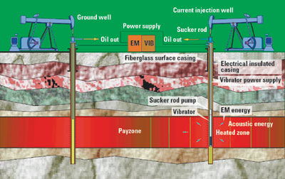 |
| Fig. 2. Typical arrangement of electrical / vibration stimulation source and production wells. |
|
Vibrations
Research related to weak elastic wave stimulations of a reservoir started in the late 1950s. Activity peaked in the early 1970s in the U.S., and in the 1970s and 1980s in the Soviet Union. However, there has been a resurgence of interest and research in both countries in recent years.
Interest in the effect of elastic waves on water, oil, and gas production dates back to observations made to find correlation between water-well levels and seismic excitation from cultural noise and earthquakes.
Numerous investigations show the effect of earthquakes on oil production. Steinbrugge and Moram (1954) described variations in oil production in Kern County during the Southern California earthquake of July 1952. Several wells showed increased casing pressure many times above normal in the first few days following the earthquake. One well showed an increased production to 34 bpd from 20 bpd, immediately after the quake, whereas another dropped to less than 6 bpd from 54 bpd.
A number of publications consider the proposed mechanisms of the effects of weak elastic waves on saturated media in detail, including: Bodine, 1954a/b, 1955; Duhon, 1964; Surguchev et al., 1975; Gadiev, 1977; Wallace, 1977; Kuzenetsov and Efimova, 1983; Kissim and Staklianin, 1984; Vakhitov and Simkin, 1985; Sadovskiy et al., 1986; Simkin and Lopukhov, 1989; Kuzenetsov and Simkin, 1990; Kissin, 1991; and Simkin and Surguchev, 1991.
Fundamentally, gravitational and capillary forces are principally responsible for the movement of fluids in a reservoir (Simkin, 1985; Odeh, 1987). Gravitational forces act on the difference in density between the phases saturating the medium, as illustrated in Fig. 3.
 |
| Fig. 3. Effect of vibrations on oil-saturated media. Acceleration of the masses by oscillating elastic sound waves. Oil acceleration is greater than water; water is greater than rock. |
|
Residual oil in a typical, depleted reservoir is generally contained as droplets dispersed in water. Density differences induce the separation of oil from water, which is a well-known effect in gravitational coalescence. Capillary forces play an important role in liquid percolation through fine pore channels. Liquid films are adsorbed onto pore walls during the percolation process. These films reduce normal percolation by reducing pore trough effective diameter. If the pore is small, the boundary film may block percolation altogether. Percolation may resume only when some critical pressure gradient is applied. Further, presence of mineralization in the percolation fluid changes the thickness of the fluid film.
Effects on oil mobility. In saturated reservoirs, water and oil phases are intermixed and dispersed within each other. The important attribute of relative permeabilities between the phases, which governs the oil yield factor, is the existence of a threshold oil saturation level, below which, the oil is immobile (Odeh, 1987; Nikolaevski, 1989). At lower oil saturation, oil breaks into isolated droplets.
Nikolaevski, 1989, speculates that exitation of elastic waves can change the phase permeability, thereby increasing mobility of the oil below saturation, So. Elastic-wave fields may reduce the influence of capillary forces on oil percolation considerably, resulting in an increased rate of migration through the porous medium. Low-frequency waves are less likely to produce non-linear elastic effects because the wave intensity (density of energy flux) is proportional to frequency squared (Nosov, 1965). However, in the presence of an alternating pressure field in which wavelength exceeds the diameter of oil droplets and gas bubbles in the water, droplets are induced to move because of their different densities (Kuznetsov et al., 1986; Sadovskiy et al., 1986).
Bjerknes forces, which are attractive forces acting between oscillating droplets of one liquid in another, induce the coalescence of oil droplets (Nosov, 1965, 13; Kuznetsov and Simkin, 1990, 129). Thus, as shown schematically in Fig. 4, continuous streams of oil capable of flow may be formed out of oil droplets dispersed with wave excitation.
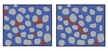 |
| Fig. 4. Vibrations cause oil droplets to coalesce, forming streams of oil in pore space (right) with resulting oil mobility increase. |
|
Depth of acoustic energy. All mechanical oscillations in a medium will eventually be converted into heat by the damping effect. Heat thus released from vibrations will raise the temperature, with a corresponding reduction in viscosity and, possibly, a partial phase transition (evaporation) of the fluids.
Reduced hydraulic friction near the oil well was reported in work performed with ultrasonic treatment of an oil well in the Soviet Union. The same effect may also be achieved with low-frequency vibrations by generating “ping” noise where the low-frequency waves are modulating higher frequency oscillations. This results in an absorption of the higher-frequency mode in the well area, giving rise to reduced hydraulic friction, while the low-frequency mode may continue deeper into the formation and contribute to effects described above.
Over the last few years, there has been growing interest in the use of acoustic fields and wave phenomena. The best prospects are those that work on the formation in the zone adjacent to the well using vibratory and wave processes. In this way, a deeper cleaning of the reservoir rocks and the most efficient injection of water and other petroleum displacing agents are obtained. The oil extraction index can be increased using better water percolation to clean the zone adjacent to the well, with low-permeability formations coming into production, and with a greater degree of displacement of oil by water or other agents.
One of the fundamental questions for developing techniques that involve wave processes is to determine acoustic energy penetration depths in the formation, sufficient to move fluids in the rock pores. As production practice shows, hydrodynamic devices and sonic generators do not always obtain a positive effect, especially in injection wells. This is explained, first, by the fact that when establishing basic parameters of generators, frequency and intensity of the acoustic field that must be determined in the concrete conditions of the deposit are not always taken into consideration. For this reason, it is of practical interest to study effective penetration depth of the acoustic waves in the formation.
Vibrating Tool Development
Even with the theory not being easy to apply, the developer faced an even greater challenge in developing the acoustic tool to generate the elastic waves. The tool, named the EurekaHammer, should not only be able to generate the necessary power, it should be able to perform over a long period without any failure in the most hostile environment. The company has so far developed two alternative tools, as shown in Fig. 5. The lower parts of both hammers have a special expansion element touching the casing so as to obtain maximum acoustic coupling with the reservoir. Dimensions for a 7-in. vibrator are shown in Table 1.
 |
| Fig. 5. Two types of vibration-generating tools developed by Eureka Oil, in cooperation with IHC Hydrohammer BV. |
|
| |
Table 1. Vibrator 7-in. dimensions
|
|
| |
Overall length, m: |
6 |
|
| |
Dia. expansion body, in.: |
6.3 (J-55) |
|
| |
Dia. above expansion body, in.: |
5.5 |
|
| |
Weight of ram, kg: |
200 |
|
| |
Impact velocity, m/s: |
5 |
|
| |
Max. impact force, Joule: |
2,500 |
|
| |
Impact time, approx., msec |
5 |
|
| |
Impact force, N: |
200,000 |
|
| |
Impact power, kW: |
500 |
|
|
The vibrator is driven by a hydraulic power pack located at the wellhead. Hydraulic-pressure oil and exhaust oil are circulated through two 16-mm hoses or pipes located in the tubing annulus in the well. Rate of blows is controlled by oil flow and may be adjusted from a blow each half second, or longer.
Impact of the ram to the extension pipe generates so-called ping noise with frequencies from 1,000 Hz downward. When electrical drive is used, a linear motor lifts and drops the ram; otherwise the operation is the same for both alternatives.
In addition to the power lines (hydraulic or electric), purging gas is supplied to the hammer from a small compressor into the ram housing, whereby the ram is running in gas. Both types of vibrators are connected to the end of the production tubing and can either be free hanging or supported. Almost any kind of lifting equipment can be used as long as the hammer can be connected to the end of tubing and/or a joint between this and the hammer. Fig. 6 shows a typical hammer installation.
 |
| Fig. 6. Typical installation of the EurekaHammer. |
|
Full-Scale Tests
The Brazilian oil company Petrobrás performed a full-scale test in 1991 – ’92, with electrical stimulation of one well in Rio Panon oil field at Rio Grande do Norte on a 15oAPI heavy oil deposit. The results are shown in Fig. 7.
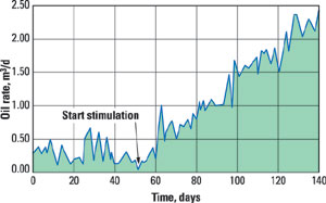 |
| Fig. 7. Full-scale test results in Petrobras’ 15oAPI heavy oil Rio Panon oil field, one well. |
|
Another full-scale test was performed in 1994 – ’95 at Cassarongongo oil field in the Bahia region of Brazil. The reservoir is at a depth of 560 m and comprises chalk sand and lime with a permeability of about 1 md.
The test was set up with one stimulation well and four surrounding wells. The central well was stimulated electrically and with vibrations, but the surrounding wells were stimulated only with electricity. The test was planned to go through two phases: 1) production of the well with no stimulation. This gave a production of about 1 m3/d; and 2) production with electrical stimulation. This work was carried out until late 1996, and it reported increased oil production of 35%. Petrobrás expected about 20% improved recovery of original oil in place.
To perform a full-scale technology demonstration in the U.S., the company purchased, in December 1997, two small oil leases in Texas. The field is a typical land-based oil field, producing from the Lower Clearfork formation. Typical reservoir data is shown in Table 2.
| |
Table 2. Reservoir data (Well 3) |
|
| |
Well depth, ft: |
4,622 |
|
| |
Payzone, ft: |
30 |
|
| |
Permeability, mD: |
50 |
|
| |
Res. press, psi: |
60 |
|
| |
Temperature, ºF: |
141 |
|
| |
Oil, °API: |
39 |
|
| |
Dead-oil vis., cP at 130oF: |
2 |
|
| |
Avg. oil prod., bpd/well: |
8.33 |
|
| |
Water prod., bpd/well: |
36.67 |
|
|
The demonstration program comprised: 1) clarifying installation procedure / methods, insulation and practical problems related to installation and field operation; 2) distribution of the electrical field in the reservoir; 3) temperature response; and 4) changes in oil/water ratio.
Preparation/installation was performed in February / March 1998, and the stimulation started March 3. Sudden distribution of the electrical field between wells and increased produced-liquid temperature were noted. No electrical safety problems were evident.
After termination of the 60-day test period, the oil/water ratio decreased to 70% water from 95%, in addition to increased oil production of 30%.
In Venezuela, Eureka Oil ASA and PDVSA entered into a contract in November 1999, with the goal of having the technology demonstrated in a heavy oil field in the Orinoco basin. The project was planned in cooperation with PDVSA, San Tome and its research department, INTEVEP, Caracas. Preparation started in spring 2000; by autumn, the wells were prepared, and installation took place in October. Eureka did the commissioning in the beginning of December, and it was planned to run for six months. Typical data for three wells is shown in Table 3.
| |
Table 3. Typical well data |
|
| |
Well depth, ft: |
2,602 |
|
| |
Oil zone thick, ft: |
40 |
|
| |
Reservoir type: |
Unconsolidated |
|
| |
Avg. perm., mD: |
10,000 |
|
| |
Avg. porosity, %: |
35 |
|
| |
Water sat., Sw, %: |
25 |
|
| |
Oil sat., So, %: |
75 |
|
| |
Res. press., psi: |
940 |
|
| |
Temperature, °F: |
124 |
|
| |
Oil, oAPI: |
10.6 |
|
|
The target wells were shut down in 1995 because of increasing water production and reduced oil production. The installation had no operational or safety problems. After the test period and evaluation of the technology performed by PDVSA and INTEVEP, PDVSA decided to move the installation to production wells for full-scale operations.
The Future
After years of research and testing of the technology, Eureka still faces great challenges in introducing its technology to the oil industry. After presenting the technology at OTC 2000, 2001 and 2002, and ONS 2000 and 2002, the company has entered into agreement with a major engineering and service company, Strong Global, Dubai, to implement the technology in a medium-heavy oil field in Syria. And it is presently negotiating delivery of the technology to China, Malaysia and Indonesia. 

The author
|
 |
Olav Ellingsen, founder and managing director of Eureka Oil ASA, Floro, Norway, graduated from the Stavanger Technical Institute in 1966 as a mechanical engineer with specialities in thermodynamics and tool construction. He has an extensive background in equipment construction, including employment with Norsk Hydro; Per Hetland Maskinfabrikk; Hatten & Jota AS; co-founder of Sogn og Fjordane Industrial Federation; co-founder and director of Industrikontakt, Ing. O. Ellingsen & Co.; founder / director of Norpigg AS; founder / director of Thermtech AS; founder of Metalica AS; founder of Ellycrack AS; and founder / director of Eureka Oil ASA. Mr. Ellingsen has received numerous awards for his inventions, and is listed in Who’s Who in the World. He participates in five company boards, and has conducted numerous lectures on business management, inventing and patenting. ind-o@online.no |
| |
|
|

