Casing Drilling successfully applied in southern Wyoming
Drilling / Well CompletionCasing Drilling successfully applied in Southern WyomingNew techniques applied in 15 new wells in BP’s Wamsutter area showed improved completions and potential for drilling-cost reductionsS. F. Shepard and R. H. Reiley, BP; and T. M. Warren, Tesco Corp.
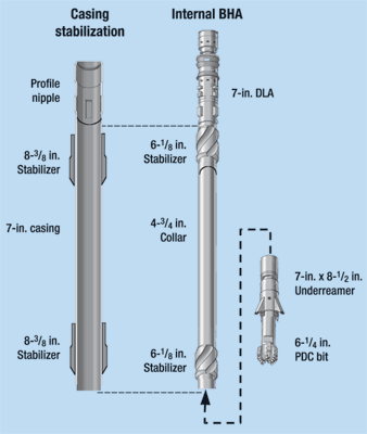
The operations of drilling surface holes to about 1,200 ft are described. Then, more details are given about production-hole drilling, with important critical data on the lessons learned from early wells, and resulting equipment / procedure improvements. While the project was terminated somewhat prematurely due to the operator’s general drilling cutback, results from the 15 wells demonstrated the viability and potential of the new process. BP used the Tesco Casing Drilling process to drill the surface and production intervals of 15 gas wells, ranging in depth from 8,300 to 9,600 ft. A five-well project was initially undertaken to pilot-test the process for drilling development gas wells in the Wamsutter area.1 The primary objective was to evaluate the potential of the technology to impact drilling operations, both in Wamsutter and, more generally, for other BP worldwide locations. The techniques proved sufficiently successful that the project was expanded to include 15 total wells, before being concluded as drilling activity in the area declined. Testing the CD technology at Wamsutter was attractive for several reasons. Operating costs there are significantly less than in many other areas where the process might be employed. Openhole logs are normally not required due to a wealth of offset well data. The project could be scheduled into a relatively active, funded drilling program. And, even though the probability of improving conventional performance and economics at this location was marginal, the additional wells were needed to maintain drilling schedules. Casing Drilling System The Tesco system simultaneously drills and cases a well using normal oilfield casing as the drillstring.2 The casing transfers hydraulic and mechanical energy to a wireline-retrievable drilling assembly suspended in a profile nipple located near the bottom of the casing. A drill-lock assembly (DLA) in the top of the drilling assembly provides mechanical (axial and torsional) coupling and hydraulic seals to the casing. It also provides a mechanism to facilitate insertion and retrieval from the casing string. The drilling assembly below the DLA terminates in a pilot bit, but may include other conventional drillstring components such as an underreamer, mud motor, coring or directional assembly. In most CD applications, an underreamer is used above the pilot bit to open the hole from pilot bit diameter to final wellbore diameter. The pilot bit is sized to pass through the casing, and the underreamer opens the hole to the size that is normally drilled to run casing. For example, a 6-1/4-in. pilot bit and 8-1/2-in. underreamer are used while drilling with 7-in., 23-ppf casing, as shown in Fig. 1.
The system utilizes a top drive to rotate the casing. Single joints of casing are picked up off the pipe rack and set in the mouse hole. The top drive is extended over the mousehole and connected to the top of the joint, which is then picked up and stabbed into the top of the casing string in the rotary table. The casing joint is drilled down using the top drive in a conventional manner. The casing string is rotated for all operations, except oriented slide drilling with a motor and bent housing assembly for directional work. Wamsutter Area Project Gas production has been under development in the Wamsutter area, located in the Greater Green River basin in South Central Wyoming, since the early 1970s. Production is primarily from the Almond Sand, located at depths of 8,000 to 10,000 ft. The Almond is a hard, tight sandstone with native pressures of about 11-ppg equivalent mud weight. It is overlain by Tertiary and Cretaceous sandstones and shales, with interbedded coals and bentonite stringers. This upper section of the production hole drills very fast with fresh water as the drilling fluid, but the pay interval is quite hard and abrasive. Conventional drilling. A number of problems may be encountered while conventionally drilling the production hole. Water flows, lost circulation in depleted zones and in a fractured zone, and bit balling in shales and bentonite beds are common. The conventional program is to set 40 ft of 16-in. conductor, drill 11-in. hole and set 8-5/8-in. casing at 1,150 ft. Then, 7-7/8-in. hole is drilled to 400 ft below the top of the Almond, where 3-1/2-in. tubing is run and cemented as the production casing. Fresh water is used as the drilling fluid down to a few hundred feet above the payzone, where it is then converted to a gel mud and weighted to about 10 ppg. A rotating head is installed before drilling into the payzone. Although the payzone is usually tight, it may give up enough gas to sustain a significant flare, when drilled slightly underbalanced. An intensive effort to reduce drilling costs at Wamsutter over the last few years has seen performance drilling with mud motors, PDC bits and underbalance techniques reduce average time to drill a typical 10,000-ft vertical well to 15.7 days. A single PDC bit is run from surface-casing depth to the top of the Almond. A Type 2 insert bit is then used to rotary drill the pay interval. Project objectives. The top priority in defining the CD technology evaluation program was to meet all safety and environmental objectives. Economic objectives were made a secondary priority to emphasize the focus on HSE; but meeting economic objectives was also essential to prove that the concept of drilling with casing was viable. An outside safety consultant was utilized on the first well to assure a seamless meshing of Tesco and BP safety programs, and to assist in developing Job Safety Assessments (JSAs) for all the special operations related to Casing Drilling. A well-control consulting firm – contracted to review all procedures relating to the underbalanced CD operation – confirmed that the work could be conducted safely and that adequate contingencies were in place before drilling commenced. Particular emphasis was placed on wireline operations used to run and retrieve the BHA with the payzone exposed. Once it was clear that the project could be conducted safely, the objectives were further defined to: capture key learnings and best practices to improve performance on subsequent wells; drill without unplanned casing tripping; and drill a useable production well to prove the new technique as a viable option to conventional drilling. Recognition that several trials are often required to successfully implement a new technology justified the multi-well program.
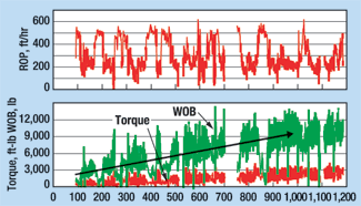
Casing Drilling rig. Tesco Rig 1, specifically designed as a Casing Drilling rig, was used for the project.3 The rig utilizes computer-controlled, hydraulically powered, rotating, hoisting and pumping systems. Fig. 2 shows the rig on a Wamsutter location. A recently developed Tesco casing clamp was used to increase the ease and efficiency of drilling with casing. The clamp eliminates need to make a threaded connection between the top of the casing and the top drive. It incorporates external slips (4-1/2 in. to 9-5/8 in.) to hold the casing axially and transmit rotational torque. An internal spear and seal assembly provides a pressure-energized hydraulic seal. The top drive and casing clamp function together to facilitate easy handling of the casing, with minimal need for personnel to use tongs on the floor. The clamp is used to make the connections up to thread-manufacturer specs, as well as rotate the casing for drilling. Surface Holes The surface hole in each of the 15 wells was drilled to about 1,200 ft with the CD system. In each case, the BHA was installed at the surface and retrieved with wireline when the casing point was reached. The cement-service company was called out before the casing point was reached and began to rig up for the cement job before the wireline was run to retrieve the BHA. An underreamer and pilot-bit assembly was used to drill the surface hole for all 15 wells. A roller-cone pilot bit was used in Wells 1 and 2, while a PDC bit was used for the remaining 13 wells. The same underreamer and cutter arms were used for the first eight wells, but could have been used for all 15 wells. Clear water was circulated directly from the reserve pit at about 350 gpm for the drilling fluid. Drilling with casing matched the ROP for conventional wells, and both downhole and surface tools proved to be reliable. Fig. 3 shows instantaneous penetration rates while drilling the surface hole on the last well. The WOB was increased as additional casing was picked up, and penetration rates ranged from 200 to 500 ft/hr. The interval was drilled in eight hours, from spud to casing point, and the cementers were rigged down 13 hr after spudding.
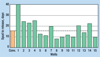
Time savings in the surface hole result from not having to handle drill collars and rig up a casing crew and run casing. A typical, conventional offset takes about 8 to 12 hr to drill the surface hole, and a total of about 19 hr from spud to primary-cement-job completion. Casing Drilling allowed the surface hole to be drilled, cased and cemented in 13 to 14 hr, with the fastest time being 11.3 hr. The BHA was retrieved successfully on 14 of the 15 wells without tripping the casing. Typically, BHA recovery required about 45 min., including surveying time. The BHA could not be recovered with the wireline in one of the surface holes because of sand accumulating above the packer cups. A change in design of the top section of the DLA prevented a recurrence of this problem. Production-Hole Drilling Production-hole drilling performance for the initial wells was considerably worse than for the conventional wells, but reached and surpassed conventional performance as issues were resolved and changes in the drilling program were implemented. Fig. 4 shows total drilling time for the CD wells compared to the average of the latest 90 conventionally drilled offsets.
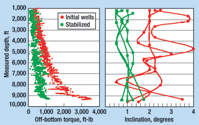
A number of engineering issues related to drilling the production section were addressed before the first well was spudded. These included considering various options for: bit cutting structures that would be most compatible with the formations; evaluating alternatives to prevent damage to the casing from buckling; selecting an appropriate casing connection; and selecting a drilling fluid.1,4 A wedge-thread connection was chosen for drilling with the 4-1/2-in., 11.6-ppf casing in the production hole. Rigid, steel-body external centralizers were used on the casing for directional control, to control buckling and prevent wear, and for cement stand-off. A 3-7/8-in. x 6-1/4-in. PDC drilling shoe was used rather than an underreamer, to open the hole from pilot-hole diameter (3-7/8 in.) to 6-1/4 in. (the drilling shoe was very similar to a large-ID core bit). The casing shoe was used because of concerns about reliability of the small underreamer. Early lessons learned. Fatigue failures of casing connections at depths of 7,728 ft and 4,885 ft on the first two wells, respectively, resulted in fishing jobs. In one case, the bottom part of the casing was recovered, but in both cases, the remainder of the well was completed conventionally with drill pipe. The cause of these failures was determined to be a combination of high cyclical stress due to lateral casing vibrations and limited fatigue resistance of the wedge thread.1 In addition to these problems, several issues with the wireline-retrievable tools were identified and resolved on the first two wells. Casing connection and casing designs were changed, and the next two wells were drilled to TD with casing, without a casing failure. This coupled connection was specifically designed for Casing Drilling, and lab tests determined it to have good fatigue properties. The casing-string design was changed to include about 1,500 ft of 23-ppf, 5-in. casing on the bottom end. This casing, threaded with a flush connection, provided additional weight to move the neutral point lower and give additional buckling resistance. Wells 3 and 4 were drilled without any problem with casing integrity or difficulty in pulling and re-setting the wireline tools. Casing on the third well was intentionally tripped out for inspection before drilling the payzone. There was no measurable wear on the 5-in. string, but couplings on about 11 joints immediately above the 5-in. were worn and replaced. Smooth, hardfaced wear bands were added to the fourth well to take care of this. Performance of the 4-1/2-in. DLA on these wells was quite adequate, showing little erosion after 191 rotating hours, while pumping at rates as high as 290 gpm. Reliability improved to the point where the DLA could be retrieved and re-set with confidence. Change to full-hole bit. Even though there was no "trouble" on the third and fourth wells, the drilling time was not competitive with conventional offsets. The drilling shoe could not be kept from balling up, and this resulted in an overall low ROP. The casing-shoe / pilot-bit combination was abandoned for the fifth well, and remaining wells were drilled with a conventional 6-1/4-in. PDC bit attached directly to the bottom joint of casing. These wells were drilled to TD and the production casing was cemented in place without retrieving the PDC bit. The profile nipple was still run above the bit to pump down a cement float in case the drilling float failed. Use of the full-hole bit immediately reduced well time sufficiently to be competitive with conventionally drilled wells, even though the casing was rotated from the surface. Wells 5 and 6 were drilled in 12.7 and 11.2 days, respectively. An experimental rupture sub was run on Well 7 to allow smaller nozzles to be run in the bit for improved bit hydraulics. This sub ruptured prematurely and required the casing to be tripped out while drilling the payzone. No abnormal wear on the casing was observed and it was re-run. Wells 5 through 7 were drilled with no stabilization immediately above the bit. Even though the deviation was benign, the torque was relatively high. A packed-hole assembly constructed of integral solid-body stabilizers inserted in the drillstring was run on Wells 8 through 15. This resulted in a significant reduction in inclination, hole tortuosity and off-bottom torque, as shown in Fig. 5.
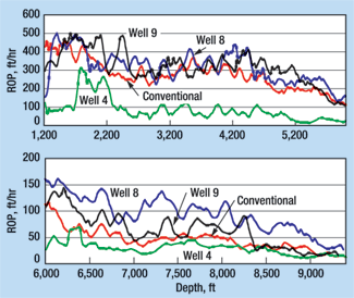
Well 8 was completed in 8.1 days – the third fastest well completed out of several hundred Wamsutter wells drilled by BP. As shown in Fig. 6, ROP in the upper 6,000 ft of hole was similar to other wells, but the most significant difference was a much better ROP in the lower part of the hole. The conventional well shown in this plot is an average of two relatively close offsets drilled in the same time frame.
The well was completed in 95 rotating hours, compared to 150 to 170 hr for a more-typical, casing-drilled well. The exact cause of the improved drilling performance of this well was not specifically determined, but it is believed to be due to some difference in the bit. Several different changes were made in the bits used in the subsequent wells to try to duplicate this result, but the result was not duplicated and, in some cases, the changes made the performance worse. Project completion. Two of the subsequent wells failed to reach TD with a single PDC bit, and thus required a casing trip to change the bit. An additional well had a connection failure of the pin on the integral stabilizer and was completed with drill pipe. The CD program was terminated after drilling 15 wells due to a reduction in the Wamsutter drilling activity. At that time, work was still in progress to find a bit that would consistently drill to TD without having a significant reduction in ROP in the payzone due to cutter wear. The overall average drilling time for the 11 wells drilled with the PDC bit was 14.0 days from spud to rig release. At the beginning of the project, wellbore stability, lost circulation and gas flows were expected to be major problems, since they are for conventional drilling operations in the Wamsutter area. Actual experience was that a CD wellbore remained stable, even when drilling underbalanced with water. The production holes reached TD with mud weights about 0.75 ppg lighter than conventional wells. No significant mud losses or well-control incidents were experienced while drilling with the casing. From limited operational experience, it appears that the process of Casing Drilling may mechanically aid building and maintaining an impermeable "filter cake" on the wellbore wall. The Wamsutter drilling performance shows that the casing is capable of functioning as a drillstring and that many of the initial concerns about CD have not materialized, or they have been resolved. The remaining impediment to drilling with small casing like that used at Wamsutter is providing an effective, replaceable cutting structure. This is not an issue for larger casing sizes because the PDC underreamers in CD applications have proven to be quite good. Since the conclusion of the Wamsutter project, considerable progress has been made on providing a multi-stage underreamer that has potential to give an adequate cutting structure for harder rocks. Conclusions The 15 wells drilled in the Wamsutter Casing Drilling pilot project demonstrated that the process can be used successfully. The process seemed to improve wellbore stability, reduce lost circulation and minimize gas influx, even when drilling with a lower mud weight than is typical for conventional drilling. Overall, CD performance at Wamsutter was comparable to the best conventionally drilled wells, but no overall cost advantage was realized. This is not surprising considering these wells are relatively simple, involve low rig costs, have limited drillstring tripping, experience no difficulty in running the casing, and they have undergone an extensive program for optimizing conventional drilling practices over the last 20 years of development drilling. Had bit performance been more consistent, the CD process could have delivered wells in less than 10 days and would have shown an economic advantage, even in Wamsutter. Well 8 was drilled to TD and cemented in just 8.1 days, which was the third-fastest well ever drilled in the area. Four of the last eight wells were drilled in less than 10 days. Based on the knowledge gained to date, the Casing Drilling system – in its current state of development – is well-suited for drilling softer formations with casing sizes of 7 in. and larger. In these situations, the penetration rate can easily match conventional rates, and the reduced tripping and drillstring handling can be used advantageously. This is particularly true in situations where difficulty may be encountered in running the casing after the hole is drilled. These time savings are significant for drilling operations with higher spread costs. Increasing confidence that the BHA can be retrieved successfully reduces the risk of using the system in these high-cost situations. Literature Cited 1 Shepard, S. F., R. H. Reiley and T. M. Warren, "Casing Drilling: An emerging technology," paper IADC/SPE 67731, 2001 IADC/SPE Conference, Amsterdam, February 27 – March 1, 2001. 2 Tessari, R. M., G. Madell, T. M. Warren, "Drilling with casing promises major benefits," Oil and Gas Journal, Vol. 97, No. 20, May 17, 1999, pp. 58 – 62. 3 Laurent, M., P. Angman and D. Oveson, "Hydraulic rig supports casing drilling," World Oil, September 1999, pp. 61 – 66. 4 Warren, T. M., P. Angman and B. Houtchens, "Casing Drilling application design considerations," IADC/SPE 59179, 2000 IADC/SPE Drilling Conference, New Orleans, Louisiana, February 23 – 25, 2000.
|
|||||||||||||||||||||||||||||
- Coiled tubing drilling’s role in the energy transition (March 2024)
- Shale technology: Bayesian variable pressure decline-curve analysis for shale gas wells (March 2024)
- Using data to create new completion efficiencies (February 2024)
- Digital tool kit enhances real-time decision-making to improve drilling efficiency and performance (February 2024)
- E&P outside the U.S. maintains a disciplined pace (February 2024)
- Prices and governmental policies combine to stymie Canadian upstream growth (February 2024)
- Applying ultra-deep LWD resistivity technology successfully in a SAGD operation (May 2019)
- Adoption of wireless intelligent completions advances (May 2019)
- Majors double down as takeaway crunch eases (April 2019)
- What’s new in well logging and formation evaluation (April 2019)
- Qualification of a 20,000-psi subsea BOP: A collaborative approach (February 2019)
- ConocoPhillips’ Greg Leveille sees rapid trajectory of technical advancement continuing (February 2019)

