Side-entry system allows capillary string intervention, remedial work
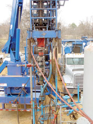
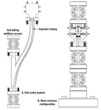
Workover TechnologySide-entry system allows capillary string intervention, remedial workNew system for clean out and remedial work with capillary strings inside production tubing simplifies workover, installation operationsJerry W. Noles, President, Advanced Coiled Tubing, Inc., Houston Over the past several years, use of capillary tubing as a means for chemical injection has become increasingly common. Capillary tubing can provide a cost-effective way of introducing soap, corrosion inhibitors or other chemicals within or below the production tubing. These small strings have proven effective as treatment conduits for a wide variety of reasons without damaging or interfering with the production string. One common use of capillary tubing has been for soap injection. The small stainless-steel line is installed down to the lower section of the wellbore to a depth where liquid accumulation is suspected. Soap is then injected, either intermittently or continuously, down the line and mixed with the wellbore liquid. The migrating gas agitates the liquid / soap mixture and forms foam. The viscosity of the foam helps to resist gas-liquid separation, allowing the liquid to be recovered at velocities below what is considered a "critical" velocity. Critical velocity is the rate below which the gas production, or flowrate, cannot overcome the produced liquid fall back. In the past, reducing the production tubing diameter or placing smaller tubes inside the existing tubing has aided in reducing gas / liquid separation (liquid fall back). These smaller diameter tubes are often referred to as "velocity strings." In some cases, however, the increased velocity can generate higher friction pressures, resulting in more backpressure than the well is capable of sustaining. When this occurs, production is either reduced or interrupted completely. Use of small capillary tubing for soap injection, in many cases, may provide an alternative to increasing production velocities, thereby providing somewhat less burden to the formation during normal production. Capillary-Line Problems Despite its many benefits, use of small capillary lines has resulted in a variety of new problems, most of which were initially unforeseen. The most common problem deals with recovery or extraction of the capillary tubing. In many cases, the soap or foam mixture will leave a residue or scale caused by gas dehydrating the foam mixture. Over time, this residual buildup or scaling can become severe enough to affect production and/or the ability to recover the small-diameter capillary tubing. The well may become completely plugged if the buildup is severe. Once the production tubing plugs, the operator loses the ability to chemically treat and remove the scale. This plugging or scaling, in severe cases, can even prevent extraction of the capillary tubing. The low-yield-strength characteristics of the small tube limit overpull capabilities, making it almost impossible to pull the string free. The capillary string, in most cases, must be recovered using a workover rig to pull the production tubing, with the smaller line trapped inside. This tubing-extraction operation may require extensive fishing operations and become costly. The high costs associated with standard workover operations have led many producers to explore through-tubing remedial techniques but, until now, the use of through-tubing recovery methods has had limited success. In most cases, the customer was left with worse problems, and still had to perform a rig workover. In many cases, wells that have production profiles in which capillary tubing offers the greatest benefit may also have the highest risk profile. Many potential candidates have limited reserves and produce at such low rates that the producer is not willing to risk the capital investment. Should the well become plugged or the capillary stuck, the low reserves may not justify an extensive workover operation. However, the customer is left with no alternative. Thus, potential risk of future recovery / extraction problems has limited use of capillary tubes by many operators. Another consideration many producers have is inability to clean or flush contaminates from the tubing or casing with the capillary tube in-place. Until recently, performing a clean out for sand removal required extraction of the stainless steel tube, then re-installation. This is such a significant consideration that many capillary companies give the producer one free extraction with the installation or purchase of the small tubing. Workover Alternative Developed Frequent occurrence of these problems over the past several years has limited use of capillary injection tubes by many producers. Numerous wells that could benefit from this technology are currently being plugged and abandoned. Alternative workover technology was needed to help reduce the producer’s risk profile and make capillary tubing use more economically viable. A new workover process and specialized equipment were developed by Advanced Coiled Tubing, Inc. (ACT) to overcome many of the problems associated with workovers involving capillary tubing. This new technology was introduced during a recent workover operation for Apache Corp. near Gilmer, Texas. In December 2001, the Apache Jones 3 well in Gilmer field went off production. The well was in a sour gas field; a 0.25-in. stainless-steel capillary tube had been installed for injection of corrosion inhibitor in the lower section of the 2-3/8-in. production tubing. When the well went offline, the company that installed the injection string was called and its removal was scheduled. During the attempted removal of the injection tube, it was discovered that the small-diameter tubing was stuck inside the production tubing. Several attempts to free the capillary were made without success, as the tube could not be pulled free within the yield limit of the small tubing. At this point, the capillary tubing was hung off and the well was left shut in. It was suspected that iron-sulfide scale might have caused an obstruction in the production tubing, resulting in the loss of production and entrapment of the injection tubing. Apache representatives began investigating recovery method alternatives. Because of the nature of the well and the plugged production tubing, it was determined that recovery of the line and the production tubing would be difficult and expensive. But company representatives learned that ACT had previously performed a clean-out operation between a small capillary tube and the production tubing during a fishing operation for another operator. It has been the common belief that, if coiled tubing (CT) were run beside or behind another conduit, it would result in the CT becoming stuck. Most people believed that the CT would helix around any other line and create a "Chinese-finger" effect, thereby preventing its removal, and complicating the recovery / workover process. The lack of alternatives warranted further investigation of this potential option. ACT was contacted by Apache, and proceeded with engineering and development to address the problem. It presented a specialized procedure that required removal of the standard hanger and installation of the developer’s side-entry system. Due to the presence of hydrogen sulfide, equipment design and manufacturing required additional time. Case-History Application After the new hanger was manufactured and tested, the existing conventional hanger was stripped off and replaced with the ACT side-entry system, Fig. 1. The new hanger configuration allowed the capillary to be positioned and hung to one side of the tree providing centerline access through a crown valve above the new hanger assembly, Fig. 2.
A special wash nozzle was designed to eliminate potential damage to the small capillary tubing and enhance the obstruction removal. Low clearance between the 0.25-in. capillary and the 2-3/8-in. production tubing limited the outer dimension of the wash nozzle. The nozzle assembly was designed to cut the material away from around the capillary without damaging it. The integrated design was then computer-modeled using the required rates, and pressures were checked to ensure they were within acceptable limits. The assembly was then fabricated and shop-tested for proper operation. Testing confirmed that projected pressure / rate data generated by the computer model was within the CT’s limits. The CT unit with 1-1/4-in. tubing was mobilized to the location and the clean-out operations began. Cleaning operations were initiated at surface in the tree areas to ensure complete removal of any material within the production tubing that could cause flow restriction. The sub-normal-pressured formation required use of either a nitrified fluid or foam to maintain circulation during the clean-out procedure. During the cleaning, CT weight was checked at 250-ft increments to provide early detection of drag problems. CT injection rates were kept low to minimize any potential damage to the capillary. The maximum CT unit load limits were also set below normal operating parameters to avoid capillary damage. No excessive drag was recorded during the procedure, and wash operations proceeded in a normal fashion. The specialized nozzle design functioned within operating expectations and material was cleaned, with better than expected rates of penetration. Wash operations extended out of the production tubing into the casing. The 1-1/4-in. CT and cleaning assembly was run to a total depth of 11,650 ft with no problems. After all of the obstructive material had been removed, the wellbore was circulated clean. The fluid pump was shut off and fluid was jetted from the well with nitrogen. The CT was removed at below-normal extraction rates, with care being taken to avoid damaging the capillary tubing. The unit was rigged down and the well was placed back on production. Total time to complete the clean-out operation was 13 hr. It should be noted that the production rates resumed at levels close to those recorded after the original well completion. As the production was restored, corrosion inhibitors were once again injected down the capillary tubing. Recent Improvements, Conclusions Since the Apache operation, additional modifications and enhancements have been made to the side-entry system. The latest version allows the system to be installed before the capillary tubing is first run. Once the side-entry is placed on the well, the capillary unit can be rigged up on the offset to deploy the tubing. The new design provides a much lower bend radius and lower frictional coefficient for the stainless steel tube at the entry point. The design allows the capillary to be moved freely in and out of the wellbore to full depth without adding any significant resistance to the tubing. Using a swab valve, the production tubing and wellbore are now accessible vertically for through-tubing operations, even under live well conditions. The new design has sufficient clearance to allow for passage of a weight bar and check valve assembly, up to 2-ft long by 0.75-in. OD. These assemblies are utilized to insert, or snub, the capillary tubing into the well against pressure. Project challenges have been to: 1) design a system for capillary-line recovery that can be used as an alternative to production-tubing extraction / replacement; 2) minimize need for fishing operations; 3) develop a cost-effective alternative to extraction / replacement of chemical injection lines during through-tubing remedial operations; and 4) identify whether the system could be used during standard clean-out operations. Further goals were to: develop a wash nozzle that could be used to remove material from around the capillary tubing without damaging the capillary; develop a cost-effective system that can be used during the initial capillary installation; and make the system compatible with any hanger system. Summarizing results: 1) it was confirmed that coiled tubing can be used as an effective through-tubing solution to free stuck capillaries and avoid extensive fishing operations; 2) the cleaning operation showed no abnormal drag that would support the "Chinese finger" effect; and 3) cost-effective systems were designed that can be initially placed on the well, allowing the capillary to be deployed through it under live well conditions. Techniques developed for these operations can be expanded to permit common wellbore interventions and wash operations with the capillary in place. Nozzle configuration was a key element to success. And through-tubing operations can now be performed without damaging the small capillary tube.
|
|||||||||||||

- Coiled tubing drilling’s role in the energy transition (March 2024)
- Shale technology: Bayesian variable pressure decline-curve analysis for shale gas wells (March 2024)
- Using data to create new completion efficiencies (February 2024)
- Digital tool kit enhances real-time decision-making to improve drilling efficiency and performance (February 2024)
- E&P outside the U.S. maintains a disciplined pace (February 2024)
- Prices and governmental policies combine to stymie Canadian upstream growth (February 2024)
- Applying ultra-deep LWD resistivity technology successfully in a SAGD operation (May 2019)
- Adoption of wireless intelligent completions advances (May 2019)
- Majors double down as takeaway crunch eases (April 2019)
- What’s new in well logging and formation evaluation (April 2019)
- Qualification of a 20,000-psi subsea BOP: A collaborative approach (February 2019)
- ConocoPhillips’ Greg Leveille sees rapid trajectory of technical advancement continuing (February 2019)

