Well control during well intervention
WELL CONTROL/INTERVENTIONWell control during well intervention Part 3 – Avoiding formation damage while pumping through coiled tubingRecommendations for implementing CT-conveyed well control within existing production tubulars to aid the user in conducting well intervention operations with minimal induced formation damageAlex Sas-Jaworsky II, SAS Industries, Inc., Houston
For those cases in which wellbore operations subsequent to the kill program are not intended to return the existing completion to active status, formation damage induced by the kill practice is generally of little consequence. However, where return of the existing completion to active status is desired, the well control operation must be conducted with a complete understanding of the pressure balance and effect of kill fluid circulation on the completion. Many practices used in performing concentric tubing well control services lead to varying degrees of formation damage and impair completion flow performance. This article discusses alternative well control kill processes and the potential for reducing formation damage by using CT well control practices. Recommendations for planning and implementing CT-conveyed well control programs within existing production tubulars are provided to guide the user in conducting well control operations with minimal induced formation damage. Well Control Practices Using Coiled Tubing There are several benefits to the use of CT services when conducting well kill operations, with the major benefits providing the ability to:
As such, circulation-type well control programs performed with CT offer a high degree of fluid placement control. In addition, the accumulations of pipe dope, rust, scale and associated debris from completion tubulars are circulated out of the wellbore during the initial pumping process and are not displaced into the exposed formation, further mitigating formation damage. When performing a circulation-type well control operation, a constant bottomhole pressure (CBP) condition should be maintained throughout the kill program. The CBP practice is intended to provide the desired balance of formation pressure through a combination of the hydrostatic pressure created within the wellbore for given fluid columns and the pressure held at surface for the prescribed choke pressure schedule. Using the CBP well control practice, the formation pressure is held at or slightly above balance during the circulation program. With the balanced bottomhole pressure condition, additional influx of reservoir fluids into the wellbore is eliminated. Of equal importance; however, is the reduction of kill-weight fluid losses into the formation, reducing the potential for induced formation damage within the completion interval. In addition, a third variable related to fluids circulation must be included in the CBP well control program analysis. During any fluids circulating program, frictional pressure losses will be generated within the wellbore annuli, which act as an additional applied pressure onto the exposed formation. Depending upon the amount of annuli pressure applied to the exposed formation, losses of kill-weight fluids can be expected, contributing to post well control formation damage, where fluid compatibility is an issue. The following discussion reviews the various design issues that should be addressed when planning and implementing well control fluid circulation operations using CT services with respect to minimizing induced formation damage. Selection of Kill-Weight Fluid The most common well control kill fluids selected for minimal induced formation damage are completion brines blended to the prescribed fluid density. Issues related to selection of the most appropriate kill-weight fluid type, chemistry and compatibility with the specified formation (with respect to minimizing formation damage) may be found in supporting published work. For the purpose of citing examples, generic completion brines will be used. Typically, completion fluids are a class of liquids described as high-density brines that behave as clear-penetrating liquids when placed across permeable formations. In addition to the high-density property needed to create the desired hydrostatic pressure balance, completion brines may be filtered through diatomaceous earth (DE) presses or filter cartridge pods to eliminate solids that contribute to formation plugging. As a result, losses of high-density brines to the formation can be expected. The loss volume will be dependent upon the near-reservoir permeability within the completion, kill-weight fluid properties and pressure applied to the formation within the annuli during the circulation program. Using a modification of the Darcy steady-state radial flow equation (Eq. 1), an approximation of the volume loss of the high-density brine to the formation can be calculated for a given pressure differential at the completion interval, assuming that data for required reservoir parameters, and the properties for the kill-weight fluid at reservoir conditions, is available.
For initial fluid losses to the completion interval, Eq. 1 must be assumed to be in an unsteady-state condition and represents liquid-liquid displacement through the completion interval. The viscosity of the kill-weight completion fluid (µ) at the given reservoir temperature should be used, along with a formation volume factor (B) of 1.00. Reservoir permeability and formation height (Kh) values obtained from production tests may be used to predict initial fluid losses to the formation due to applied wellbore annuli pressure. For example, a reservoir having a Kh value of 5,000 md-ft and skin factor (S) of 5.0 is subjected to a kill program using a 10-ppg CaCl2 completion brine having a viscosity of 0.50 cP at a reservoir temperature of 214°F. Assuming a reservoir drainage radius of 1,000 ft and a wellbore radius of 0.54 ft, the predicted amount of completion brine in bpm lost to the formation per psig applied annuli pressure is shown below.
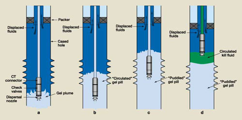
In the above example, an estimated 0.0034 bpm of brine is displaced into the formation interval for every one psig of differential pressure applied from the wellbore to the reservoir. For a circulation program in which a wellbore pressure imbalance of 100 psig is developed within the annuli (through frictional pressure losses or applied surface pressure), the imposed differential pressure against the exposed formation yields an estimated kill-weight fluid loss rate of 0.34 bpm to the completion interval. Fluid Loss Control For CT well control operations, the loss of kill-weight fluid to the formation may pose significant problems related to surface tankage volume availability, increased cost for replacement of high-density brine volumes and maintaining the desired fluid circulation / displacement rates within the wellbore. In the example fluid loss prediction seen above, a 240-min circulation kill, generating a constant annular frictional pressure loss of 100 psig above the balance pressure, will result in an estimated 82 bbl of kill-weight fluid lost to the formation. Since CT well control operations typically are conducted with limited fluid volume tankage available at surface, the well kill program must take into consideration the volume of fluid loss anticipated during the circulation program. A secondary problem can occur when attempting to perform a well kill program within a wellbore where part, or all, of the exposed completion interval is gas bearing. In this situation, fluid losses to the formation will occur as the result of gas-liquid override, regardless of the pressure balance maintained within the wellbore. Due to differences in fluid density and viscosity, clear-penetrating liquids will permeate into the completion interval, providing an avenue for gas to override the liquid and enter the wellbore. As this gas influx migrates to surface, the expansion of gas will displace wellbore liquids to the formation. This reduction in hydrostatic height of the fluid column increases the underbalanced condition within the well and promotes additional gas influx, compromising the well control effort. In completion intervals where excessive fluid losses are expected due to high permeability or gas-liquid override, it is recommended that a fluid loss control program be incorporated into the well control operation. The fluid loss prevention method should impose minimal damage to the formation and be removed easily prior to or during well production. The fluid loss mechanisms described below are designed to allow well control kill operations to be conducted with a minimum of induced formation damage. These include viscous gel pills, graded-sand plugs, and mechanical plugs or packers. Gelled pills. In general, these fluid loss control mechanisms are brine viscosifiers, which include linear gels and cross-linked gels. These pills may be blended with the high-density brine selected as the kill-weight fluid or a compatible brine and serve to significantly reduce the amount of fluid loss to the formation by creating a temporary barrier of high-viscosity media across the exposed formation. The placement of this type of fluid loss control pill does not restrict access to the completion interval if intervention work is required subsequent to the kill program. Due to the complex nature of these viscous gels, it is critical that compatibility tests are run between the selected gel system and the formation fluid / rock chemistry to ensure that secondary damage due to precipitation does not occur. The removal process may require external breakers or contact with low-pH acid solutions. Sized-salt pills. Another mechanism used to control fluid loss is a saturated graded-salt pill. This type of pill is also blended with the kill-weight brine and used to create a barrier to fluid flow across the exposed completion interval by forming a mechanical bridge with the salt particles. The placement of a sized-salt may not restrict access to the completion interval if intervention work is required following the kill program due to settling. The removal process may require a high-energy wash with an undersaturated solution to dissolve the salt bridging particles. Graded-sand plugs. In some situations, a graded-sand plug may be circulated down the CT string and placed across the completion interval to blanket the exposed formation. This type of plug provides protection from formation damage that could occur during well service work performed subsequent to the well kill program. In general, the smaller the sand sieve size, the more effective the plug for fluid loss control. However, small sand grain sizes may travel into the pore spaces of the exposed formation, creating a secondary damage mechanism. Therefore, sand selected for this service should have high sphericity (roundness) and be commercially sieved to a mesh range that will bridge against the formation face and minimize sand entry into the pore spaces when placed across the completion interval. Mechanical plugs and packers. Depending upon the post-well-kill service to be performed, the completion interval may be mechanically isolated from surface with the use of through-tubing plugs or packers. If access to the completion interval is not required, then an assessment may be made to determine if mechanical isolation will provide the desired barrier to fluid loss and mitigation of formation damage for the given well. This isolation option requires that the borehole ID be within the applicable size range of the inflatable plug or packer device, which will be transported through and set in the existing completion tubulars. Although this isolation mechanism should create the necessary pressure barrier within the wellbore, the well control program still should incorporate kill-weight fluids circulated above the inflatable device to create a hydrostatic balance across the elastomeric sealing elements. Further sealing efficiency may be obtained by spotting a sand plug on top of the inflatable device prior to circulating the kill-weight fluid into the wellbore. Kill Fluid Circulation and Placement The unique ability of continuous pumping through CT, while manipulating the position of the tubing within the wellbore, provides the means to control the placement of the fluid loss treatment with a high degree of accuracy. Depending upon completion design and wellbore orientation, the kill-weight fluid circulation program may require added preparation to ensure effective placement of the kill fluid and/or viscous gel pill. Proper well control programs require that the wellbore segment located below the base of the completion interval be prepared to support a column of kill-weight fluids without the possibility of gravity segregation and/or contamination. Prior to commencing well control operations, the actual plug-back depth should be determined and the fluid volume to fill the wellbore segment between the base of the completion interval and plug-back TD should be calculated. If the completion design allows for mechanical isolation of the wellbore below the exposed interval, then a through-tubing type plug or packer may be set at a depth that reduces the volume of the exposed wellbore segment. However, if it is not feasible to mechanically isolate the lower wellbore segment, then an additional circulation operation should be conducted to displace the fluid below the completion interval with the required kill-weight fluid density. Placement of viscous gelled pills. In a typical viscous-gel pill placement program, the CT fluid nozzle is located within the wellbore at a depth below the exposed completion interval. The gelled-pill treatment volume is circulated down the CT string to the nozzle, with displaced wellbore fluids returned and captured at the surface. Based on observed fluid pumping rates through the CT string, the arrival of the fluid loss control pill at the CT nozzle downhole can be accurately timed. When the fluid loss control pill begins to exit the CT nozzle, a specified volume of the pill is displaced into the wellbore to create an interface between the nozzle and the resident wellbore fluids, Fig. 1a.
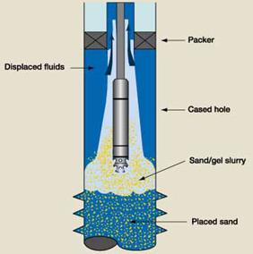
If the height of the completion interval to be treated is short (<30 ft), then the position of the CT nozzle may remain stationary, and circulation of the viscous gel pill continued until the desired gel column height is achieved. To ensure that the gelled pill is properly placed across a longer completion interval, the CT string typically is manipulated during the circulation program. This fluids placement practice, commonly described as "puddling," is conducted by slowly pulling the CT nozzle up the wellbore at a speed commensurate with the fluids pump rate, which keeps the position of the gelled pill interface at the desired height above the nozzle, Fig. 1b. This operation ensures that the pill is effectively placed across the completion interval with minimal contamination from resident wellbore fluids. Note that the description of the above puddling process is valid for vertical and moderately deviated wellbore orientations. In highly deviated and horizontal completion intervals, gravity segregation of the kill-weight gelled pill requires some modification to this procedure. For this application, the CT nozzle should be run to the plug-back TD of the horizontal borehole and circulation of the prescribed kill-weight gelled pill initiated. The circulation of the high-density viscous pill should fill a minimum of 80% of the horizontal borehole volume before commencing the CT puddling procedure. During this initial circulation phase, the less dense resident fluids in the borehole can segregate into the ullage space at the top of the horizontal borehole. Once a sufficient volume of the gelled pill is placed in the borehole, pump rate is increased, creating a high-energy plume at the CT nozzle. Upon extraction of the CT nozzle, remaining resident fluids are displaced forward and ultimately circulated out of the wellbore. To ensure that the entire completion interval is covered by the fluid loss control treatment, the calculated volume of pill needed should include excess volume, which will accumulate above the top of the completion interval, Fig. 1c. The desired height of the viscous gel pill above the completion interval is a function of the predicted effectiveness of the gel pill for the target formation. As such, the recommended height of the pill in excess of the completion interval top should be determined on a job-by-job basis for the respective gel type selected. The specified pill height above the completion interval should serve as the upper position where the CT nozzle will be placed when conducting circulation of the clear-penetrating kill-weight fluid, Fig. 1d. Placement of sand plugs. Where placement of sand plugs is desirable for use as a fluid loss control mechanism, planning must include onsite blending of the sieved sand within the desired linear gel, minimum pump rate through the CT string (to ensure pumping control of the slurry) and volume of the individual slurry batches to be pumped. In general, the slurry batch volume should be sized no larger than the capacity of the CT string deployed within the wellbore. This will allow for measured displacements within the wellbore and minimize sand settling within the CT on the reel at surface if the nozzle becomes plugged during the placement program. Once the slurry volume reaches the nozzle, the CT should be retrieved up the wellbore at a speed commensurate with the sand settling rate for the given gel concentration, Fig. 2. Note that the pump rate of the sand slurry should not create an annular velocity that exceeds the sand settling rate for the given gel system.
After the
volume of slurry is displaced through the CT string, maintain
circulation and displace a volume of fluid equal to the slurry volume
previously pumped. If a fill-up depth check is warranted, then the
pumps should be shut down and the CT run slowly into the wellbore to
tag the top of the sand plug. The slurry mixing and pumping process
should be continued until the top of the sand plug reaches the desired
depth within the wellbore. Sand plug height above the completion
interval should then serve as the upper position where the CT nozzle
will be placed when conducting circulation of the clear-penetrating
kill-weight fluid. Literature Cited 1 World Oil’s Coiled Tubing Handbook, 3rd Edition, Gulf Publishing Company, Houston, Texas, 1998. 2 Sas-Jaworsky, A., and A. Ghalambor, "Considerations For Conducting Coiled Tubing Well Control Operations to Minimize Formation Impairment," SPE paper 58792, SPE International Symposium on Formation Damage Control, Lafayette, La., February 23 – 24, 2000. 3 Bishop, S. R., "The Experimental Investigation of Formation Damage Due to the Induced Flocculation of Clays Within a Sandstone Pore Structure by a High Salinity Brine," SPE paper 38156, SPE European Formation Damage Conference, The Hague, Netherlands, June 2 – 3, 1997. 4 Foxenberg, W. E., et al., "Effects of Completion Fluid Loss on Well Productivity," SPE paper 31137, SPE International Symposium on Formation Damage Control, Lafayette, La, February 14 – 15, 1996. 5 Houchin,L. R., et al., "An Analysis of Formation Damage by Completion Fluids at High Temperatures," SPE paper 23143, Offshore Europe Conf., Aberdeen, September 3 – 6, 1991. 6 Baijal, S. K., et al., "A Practical Approach to Prevent Formation Damage by High-Density Brines During the Completion Process," SPE paper 21674, Production Operations Symposium, Oklahoma City, Okla, April 7 – 9, 1991. 7 Morgenthaler, L. N., "Formation Damage Tests of High-Density Brine Completion Fluids," SPE paper 13811, SPE Production Operations Symposium, Oklahoma City, Okla., March 10 – 12, 1985. 8 Allen, F. L., et al., "Initial Study of Temperature and Pressure Effects on Formation Damage by Completion Fluids," SPE paper 12488, Formation Damage Control Symposium, Bakersfield, Calif., February 13 – 14, 1984. 9 Syed, A. Ali, et al., "New Test Identifies Completion Fluid Compatibility Problems," Oil & Gas Journal, August 25, 1997, pp. 95 – 101. 10 Hodge, R. M., "HEC Precipitation at Elevated Temperature: An Unexpected Source of Formation Damage," SPE paper 38155, SPE European Formation Damage Conference, The Hague, Netherlands, June 2 – 3, 1997. 11 Hardy, M., "The Unexpected Advantages of a Temporary Fluid-Loss Control Pill," SPE paper 37293, SPE International Symposium on Oilfield Chemistry, Houston, Texas, February 18 – 21, 1997. 12 Himes, R. E., et al., "Reversible Crosslinkable Polymer for Fluid-Loss Control," SPE paper 27373, SPE International Symposium on Formation Damage Control, Lafayette, La., February 7 – 10, 1994. 13 Johnson, M. H., "Completion Fluid-Loss Control Using Particulates," SPE paper 27371, SPE International Symposium on Formation Damage Control, Lafayette, La., February 7 – 10, 1994. 14 Blauch, M. E., et al., "Fluid-Loss Control Using Crosslinkable HEC in High-Permeability Offshore Flexure Trend Completions," SPE paper 19752, 64th SPE ATCE, San Antonio, Texas, October 8 – 11, 1989. 15 Chambers, M. J., "Laying Sand Plugs With Coiled Tubing," SPE paper 25496, Production Operations Symposium, Oklahoma City, Okla., March 21 – 23, 1993.
|
||||||||||||||||||||||||||||