Innovative construction of a Level 6 multilateral well
DRILLING/WELL COMPLETIONInnovative construction of a Level 6 multilateral wellA dual-leg junction with compressed branch legs is run on primary casing, then legs are expanded to allow drilling and completionRobert E. Snyder, Editor
Described here is a preformed, field-tested, dual-leg Level 6 junction that has been developed using a novel metalforming technique. The junction construction process starts when a compressed-shape, dual-leg junction is run in the hole at the bottom of the parent casing. Afterwards, a wireline-conveyed expansion tool post-forms the junction in a fully controlled and closely monitored process. The result of this simple construction process is a junction with an overall mechanical integrity and a known geometry. This article describes the dual-leg junction and process-related system tools, then overviews the full construction process of a multilateral well using the preformed dual-leg Level 6 junction. Summaries of an experimental installation in Oklahoma and an onshore field installation in Brazil for Petrobrás are presented. And plans for an offshore Brazil project and testing of a larger-diameter system are noted. Note: This condensed article summarizes several tool features discussed and illustrated in greater detail in paper SPE 63116, presented at the 2000 SPE Annual Technical Conference.1 The original document should be reviewed for more specific design data. Information and illustrations for the following summary article were supplied by Schlumberger. Introduction At first glance, the multilateral option offers immediate advantages over single-bore wells since it provides increased reservoir exposure at a reduced cost. However, a more detailed analysis of this option shows that the greater technical complexity involved in the construction process of a multilateral well can offset its economic advantages. Multilateral applications have been historically constrained by the complex construction process of the junction, and the fact that overall mechanical integrity and detailed geometry of the junction is not always known and predictable for the lifetime of the producing reservoir. A Level 6 junction, as defined by TAML, must provide both mechanical and hydraulic integrity. A simple Level 6 junction comprises two adjacent tubular joints at the bottom end of a parent casing. Such a design simplifies the construction and provides overall mechanical integrity. Conversely, it also leads to a low branch-casing to parent-casing diameter ratio, resulting in loss of two or more intermediate casing sizes. This geometry also requires a larger hole size to accommodate its outer dimensions. In summary, the sudden jump from one large casing size (the parent casing) to a much smaller one (the branch casing) considerably limits the system’s application. The Schlumberger RapidSeal* multilateral system addresses the limitations of a simple Level 6 junction design using novel metal-forming technology. The dual-leg design optimizes the branch / parent diameter ratio, minimizes casing-size loss and eliminates need for larger diameter boreholes for installation. As will be described, junction legs are initially compressed, so that the overall junction outer diameter is comparable to that of the parent casing, and less than the sum of their final outer diameters. Symmetrical arrangement of the two outlets ensures that dog-leg severity in the transition zone from the parent casing to both branches is minimized, allowing standard drilling and completion tools to seamlessly drift through it. Finally, the use of a wireline expansion tool ensures that the downhole junction reforming process is fully controlled and monitored in real time. This simple, speedy and debris-free construction process results in a known final junction geometry. Junction Assembly Description The purpose of the junction is to achieve a structural link between a parent casing and two lateral legs, while providing hydraulic isolation. Two high-ductility formable legs are welded onto the stiffener, the junction’s structural member, which is made of high-strength material, Fig. 1. The proprietary welding process ensures full penetration of the welding bead along the complex geometry of the stiffener-leg interface. This unique, hybrid design of the dual-leg junction increases its resistance to both internal (burst) and external (collapse) pressure loading.
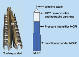
The leg subassembly is connected to the parent casing by an adapter that provides a smooth transition from the single-bore to the dual-bore sub-assembly. The bottom part of the junction assembly features a guide shoe made of a fiberglass envelope, with a steel frame cemented inside the envelope. This guide shoe functions as a standard casing shoe, and also provides protection to the formable legs during running of the casing string. In addition, its steel structure acts as a whipstock in guiding the drilling bottomhole assembly (BHA) out of the junction outlets during drilling of the branches. During the forming process, the geometry of the junction is collapsed to fit entirely in a pre-established outer diameter envelope according to the size of the parent casing. Only the ductile legs sustain plastic deformation, while the stiffener remains undeformed. Because it is critical to the later expansion phase, the operation is performed in a special press that guarantees tight tolerances on the compressed geometry of the junction. Throughout the well-construction process, some tools, such as the wireline-conveyed expansion tool, need to be inserted in the junction. Others, such as the drilling deflector used to guide drilling and completion assemblies into the lateral branches, need to be oriented with respect to the junction outlets. An orienting keyway within the parent casing string is used to achieve the necessary tool orientation. Three tubulars are used to build the indexing casing coupling (ICC).1 The assembly is essentially a short casing pup joint with an orienting keyway and a locating profile in its inner diameter. The casing coupling is then made up to the top of the junction assembly at a known distance and orientation with respect to the orientation of the junction outlets, using timed threads. The tools that need to be oriented with respect to the junction outlets have an orienting key that rides the casing coupling’s orienting keyway. The key / orienting-keyway interaction induces a tool rotation that ends once the tool is in the desired orientation with respect to the junction outlets. Certain tools, such as the drilling deflector, need to be left in the casing coupling once they have been oriented. The locating profile in the casing coupling is used to lock system tools in a known position and to prevent their movement during the well-construction process. Two sizes of the RapidSeal system have been developed and are in different developmental phases. The 9-5/8 x 7 x 7 in. has been successfully installed for a client in a land location, and the 13-3/8 x 9-5/8 x 9-5/8 in. will be tested for the first time in 3rd Quarter 2001. System Deployment The parent section (12-1/4 or 17-1/2 in.) is drilled using standard procedures and equipment, and a 60-ft section of it is under-reamed to a pre-established diameter (17-1/2 or 24 in.), depending on size of the parent casing (9-5/8 or 13-3/8 in.). Branch expansion. The junction is placed within the under-reamed interval and the junction expansion tool is run in the hole using wireline. The modular junction expansion tool (MJET), Fig. 2, is oriented using the ICC. The two expansion legs enter the compressed junction outlets. A positioning sensor indicates in real time when the MJET legs reach their final position. The junction orientation sensor within the tool measures orientation of the outlets’ plane with respect to the hole’s high side.
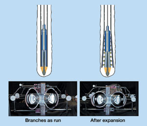
Once all measurements have been taken, the MJET is activated. At this point, and using proven MDT* (Modular Dynamics Tester) technology, an array of hydraulic pistons generate forces in the order of 500 Mlb to 1.4 MMlb, depending on junction size. These pistons push saddles that, in turn, press against the junction legs, restoring their original circular geometry within 45 min., Fig. 3.
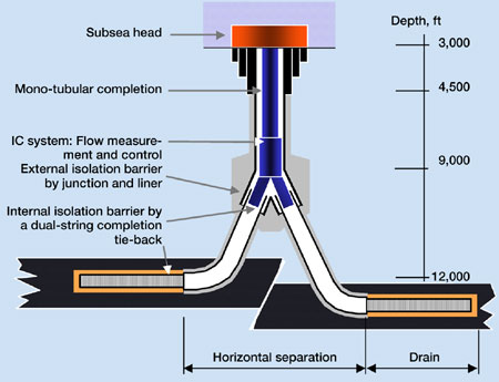
Eight potentiometers monitor opening of the pistons, indicating quality of the post-forming process, and measuring the outlets’ final geometry. Sensors embedded in the hydraulic system constantly monitor opening forces and hydraulic pressures. All data gathered during the post-forming process is transmitted up-hole via wireline in real time. This data is logged and saved into the surface acquisition system for posterior analysis and quality control of the opening process. Once the junction is fully expanded, the MJET is retracted and pulled out of the hole. To minimize stuck-in-hole risk, the tool has several safety features. If power to the tool is lost or purposefully cut, the tool automatically retracts to its closed position. Although highly improbable, it is possible to imagine a situation by which the MJET gets stuck in the hole. In this case, the wireline cable is parted and recovered, and then, using an overshot, the wireline toolstring is recovered. If the string remains stuck, pulling on it will sever the hydraulic lines, causing the piston arrangements to retract due to a loss in hydraulic force. Casing cementing. After the wireline toolstring is removed from the casing, a retrievable cement retainer is run and set within the junction assembly. The junction and parent casing string are then cemented in place. After cement has cured, the custom-made retrievable cement retainer is recovered, and the drilling deflector is run in the hole and set inside the ICC locking profile. The junction legs can be selectively accessed using a retrievable, pipe-conveyed drilling deflector, which is run in the hole using a hydraulically-operated running tool. As the deflector passes through the ICC, the orienting key in its outer diameter induces tool rotation. Placement of the orienting key on the deflector body determines which leg is accessed. Once the deflector reaches its desired orientation, it is anchored to the ICC locking profile, using a hydraulic procedure that takes less than 20 min. and provides pressure feedback. Branch drilling / completion. Standard drilling assemblies can now be run in the hole to commence branch construction. A 6-1/8-in. drill bit is used in the case of the 9-5/8-in. junction, whereas an 8-3/4 or an 8-1/2-in. bit is used with the 13-3/8-in. junction. Bi-centered bits can also be used, as long as their outer diameter while not rotating complies with junction-outlet, nominal drift. Once the lateral drilling phase is completed, and with the drilling deflector still in place, the branch can be completed in several ways, including fully cemented 4-1/2-in. or 7-in. liner strings, slotted liner, screens, etc. The lateral liner is always hung from the junction outlet using a custom-made liner hanger packer that is run and set using a hydraulic tool.1 A positioning sub is used in the liner-hanger-packer running assembly to ensure that it is properly placed within the junction outlet, prior to initiating the setting procedure. A versatile, custom-made liner cementing tool allows for both stage and standard cementing of the 4-1/2-in. liner string. This configuration provides isolation from the reservoir up to the junction, which is normally placed just above the payzone and at any desired inclination. In the case of the 13-3/8-in. junction, the lateral branches would be completed using 7-7/8 or 7-in. liner strings. A custom-made liner-hanger packer is used to hang the liner strings from the junction outlets, and a custom-made cementing tool is used if liner cementing is needed. The Dual Access completions system allows either commingled or separate lateral production. The basic completion system comprises two stingers that seal inside the lateral branches using: 1) seal bore extensions and seal stacks; 2) an orienting device that ensures correct insertion of system legs into junction legs; 3) a discriminator used in the case of commingled production to selectively access each lateral for workover purposes; and 4) a packer that isolates the annulus between production strings and parent casing. The completion options and scenarios are varied and include intelligent completions that, when combined with a multilateral well, can provide a substantial increase in productivity and valuable reservoir management tools. Installation Track Record An experimental well was built in Oklahoma during 4th Quarter 1999.1 A RapidSeal junction was successfully installed in a deviated well, expanded and cemented in place. Two 6-1/8-in. directional branches were drilled out of the junction. The first was completed with an uncemented 4-1/2-in. liner string, whereas the second was completed with a cemented 4-1/2-in. liner string. The main objective of this well was to test all system tools before a commercial field installation. All tools were used successfully during this first full-system deployment. The first commercial field installation was performed in a land well in Brazil for Petrobrás. A RapidSeal junction was installed above the reservoir at 32° inclination, expanded and cemented in place. Two 7-in. lateral branches were drilled using standard Schlumberger Anadrill downhole motors and Bicentrix* PDC bits from Reed-Hycalog. Both laterals were directionally drilled and completed using cemented 4-1/2-in. production liner strings providing isolation down to the reservoir. The Dual Access completion system was run in the hole for testing purposes. After extensive and successful testing of the functional features, this completion equipment was fully retrieved in order to perforate and complete the multilateral well as per Petrobrás specs. This installation marked the first worldwide application of a 9-5/8 x 7 x 7-in. Level 6 junction, placed above the reservoir, with fully cemented liners extending into four different targets. Petrobrás and Schlumberger are currently collaborating and developing operating procedures for installation of a 9-5/8 x 7 x 7-in. system offshore Brazil that will take place in the near future. Fig. 4 illustrates application of the system in a deepwater application.
The 13-3/8 x 9-5/8 x 9-5/8-in. multilateral system has been qualified in lab conditions. An experimental well will be constructed using this system in 3rd Quarter 2001. And there are plans for a first commercial field installation in 4th Quarter 2001. In summary, the Level 6 systems described here show
promising results in terms of performance and user satisfaction. The main advantage over other multilateral
levels is the reduction in risk based on a simple downhole junction construction process. When compared to
other possible Level 6 junction geometries, the RapidSeal design optimizes the parent-to-branch ratio,
minimizing casing size loss. The stiffener and leg hybrid design allows the system to reach suitable pressure
ratings. Finally, the symmetrical design ensures a gradual transition from the parent bore to each of the
branches, allowing standard drilling and completion assemblies and tools to seamlessly drift through the
junction.
Literature Cited 1 Ohmer, H., J. M. Follini, R. Carossino and M. Kaja, "Well construction and completion aspects of a Level 6 multilateral junction, paper SPE 63116, presented at the 2000 SPE Annual Technical Conference and Exhibition, Dallas, Texas, October 1 – 4, 2000. |
||||||||||||||||||
- Applying ultra-deep LWD resistivity technology successfully in a SAGD operation (May 2019)
- Adoption of wireless intelligent completions advances (May 2019)
- Majors double down as takeaway crunch eases (April 2019)
- What’s new in well logging and formation evaluation (April 2019)
- Qualification of a 20,000-psi subsea BOP: A collaborative approach (February 2019)
- ConocoPhillips’ Greg Leveille sees rapid trajectory of technical advancement continuing (February 2019)

