Well control during well intervention
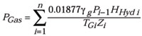
Well Control / InterventionWell control during well interventionPart 4 – Selecting proper coiled tubing well control equipmentRecommended well control stack and flow control device configurations are given, in addition to considerations for properly sizing CT string ODAlex Sas-Jaworsky II, SAS Industries, Inc., Houston The design of concentric tube well servicing technology provides the means to conduct well intervention operations while maintaining required barriers for pressure and fluid flow control at the surface. For coiled tubing (CT) operations, the primary mechanism for maintaining pressure and fluid containment is the purpose-built well control stack working in combination with fluid flow control devices in the surface treatment piping. Due to the specific equipment component functions and operating practices used in underbalanced CT applications, well control practices require greater attention during preparation and implementation. This article provides an overview of the recommended CT well control stack and flow control device configurations for defined pressure control conditions, plus considerations for proper OD sizing of the CT string. Maximum Surface Pressure Assessment When selecting the appropriate CT well control stack pressure rating, an assessment must be made to determine the maximum surface pressure expected for the prescribed service. The first step requires that a hydrostatic pressure calculation be performed to determine maximum anticipated surface pressure (MASP) within the wellbore. API RP 5C7 stipulates that the MASP, which is defined as the highest pressure that may be encountered at surface for the given operation, be used to determine the pressure rating of the well control stack and related riser components. For well intervention services, the MASP is typically found by subtracting the hydrostatic pressure exerted by a column of compressed dry gas (as measured from the surface-to-reservoir true vertical depth) from the static pressure of the formation(s) open to the wellbore. The hydrostatic pressure exerted by a column of dry gas (PGas, psig) may be calculated using Eq. 1, where gg represents gas specific gravity, Pi is hydrostatic pressure of the incremental gas column height in psig, HHyd is true vertical height of the gas column increment in feet, TG is gas temperature in °R and Z is gas compressibility factor.
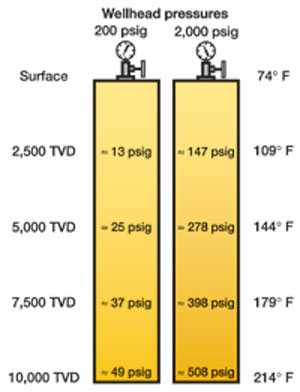
Through summation of gas column height increments, PGas can be calculated for a given wellhead pressure (P0) from surface to the desired depth for the specified conditions. This series of calculations requires trial and error iterations in order to determine P0 (in psia) which, when added to the hydrostatic pressure of the gas column, will balance the reservoir pressure. An example illustrating the predicted density of columns of 0.65-S.G. compressed natural gas is offered in Fig. 1 for wellhead pressures of 200 psig and 2,000 psig, respectively, assuming a temperature gradient of 0.014°F/ft. This example demonstrates how the gas density increases at increasing TVD, yielding the respective hydrostatic pressures at depth when the natural gas column is subjected to the specified amount of pressure at surface.
Once MASP is predicted, the next step is to determine the maximum expected surface pump pressure exposed within the stack prior to confirming the pressure rating of the surface well control equipment to be used. For this assessment, it is assumed that pressure integrity of the tube above the stripper has been compromised, and a circulation kill program must be performed. In this case, CT must be hung within the slip rams and mechanically separated using the shear rams. Once CT has been sheared, the tube is pulled upward to clear the blind rams position in the well control stack, and the blind rams are closed. The blind rams form a pressure barrier within the well control stack above the sheared CT and provide a means for pumping down the CT when conducting a circulation kill program. This pumping pressure evaluation requires that OD, ID and length of CT in the well be defined, along with the density and rheology of the fluids to be pumped during the prescribed service or well control program. This exercise must incorporate the desired performance of the treatment fluids pumping program, along with the predicted behavior of the kill-weight fluids when circulated to achieve pressure balance within the wellbore. The maximum expected pump pressure, when added to MASP, cannot exceed the working pressure rating of the well control stack for the prescribed service. Well Control Stack Components As previously discussed, the well control stack serves as the primary barrier for maintaining isolation of wellbore pressure and fluids at the surface in CT services. The minimum CT well control stack assembly components defined in API RP 5C7 are shown below:
Options are allowed for combining the blind and shear ram functions into a single ram operation. Similarly, the slip and pipe ram functions may be combined into a single ram. The orientation and function of the components listed above should be considered as the minimum well control stack configuration for CT service operations. Additional CT well control components recommended within API RP 5C7 include a flow tee or cross, along with a safety pipe ram mounted below the quad-ram stack. If the wellhead crown valve is incapable of holding pressure from above for pressure testing purposes, a separate gate valve should be installed at the base of the well control stack riser, directly above the crown valve. A detailed review of the function and performance expectation for each well control component is outlined in API RP 5C7, with recommendations offered for pump, kill and choke / returns surface piping. As acceptable limits for CT service and pumping pressures increased, the selection of appropriate well control equipment pressure rating required additional attention. The guidelines shown in Table 1 classify the well control stack pressure service category (PSC) ratings for CT intervention services where bend-cycling occurs with the tube exposed to the designated MASP shown below. For all service categories, the difference between MASP and expected pump pressure offered in Table 1 roughly translates to the maximum amount of frictional pressure loss expected when circulating kill-weight fluids through the remaining segment of CT hung within the well control stack, within the annuli and back to surface. For example, the PSC 1 case suggests that the increase in pump pressure allowed for performing the circulation kill is 1,500 psig (see Table 1).
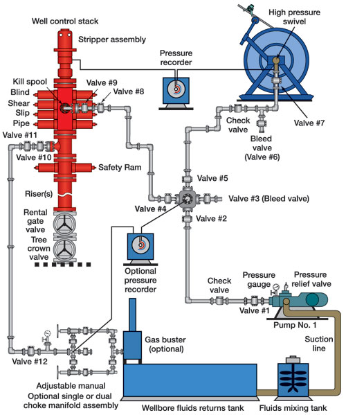
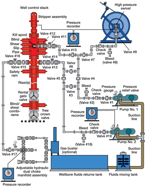
The various service categories of well control equipment shown in Table 1 are discussed below and are offered as a guideline for use in determining the level of preparation for a prescribed CT service. As the service category rating increases, performance requirements stipulated for the lower categories must be maintained, with the additional performance requirements determined by the service and pressures expected during the operation. Service category 1. In a PSC 1 environment, maximum recommended surface wellbore pressure is 3,500 psig, with a maximum surface pumping pressure of 5,000 psig through the kill line and CT. The PSC 1 category (Fig. 2) requires that the well control stack and related piping be rated to a minimum working pressure of 5,000 psig. The surface piping requirements for the pump, kill line and returns / choke lines conform to API RP 5C7, with the addition of a pumping cross to direct pumped fluids to the CT reel or the kill spool. The manually adjustable dual choke allows service to be diverted to the back-up choke if the primary choke fails. A separate pressure recorder may be used to record pump and choke pressures independent of the CT unit.
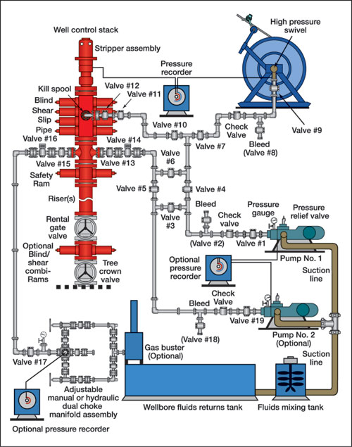
Service category 2. In a PSC 2 environment, maximum recommended surface well pressure is 7,500 psig, with a maximum surface pumping pressure of 10,000 psig through the CT. For the PSC 2 category, the well control stack and related piping should have a minimum working pressure rating of 10,000 psig, with the recommended surface well control components seen in Fig. 3.
The surface piping includes additional pressure isolation valves and a pumping manifold to allow for directing the pumped fluids to the CT service reel and the flow cross on the well control stack. Should the situation dictate that CT be sheared to allow the blind rams to be closed, the kill program can be conducted by directing the pumped fluids to the kill spool and down the CT string remaining within the wellbore, to the flow cross on the well control stack, or both. The surface piping to the well control stack for PSC 2 operations should be connected through flanged, high-pressure valve assemblies. In addition, the outboard valve on the flow tee or flow cross should be equipped with a remote hydraulic actuator for rapid closure in an emergency. The dual-choke manifold may be manually or remotely adjustable using hydraulic actuators. A separate pressure recorder may be used to record pump and choke pressures independent of the CT unit console. Depending upon prescribed service and wellbore MASP, blind / shear combination rams should be considered for use within the well control stack riser assembly. In addition, a second high-pressure pump should be considered as a backup pump or emergency kill pump. Service categories 3 and 4. In the PSC 3 case, the maximum recommended surface well pressure is 10,000 psig, with a maximum surface pumping pressure of 12,500 psig through the CT. For the PSC 4 case, maximum recommended surface well pressure is 12,500 psig, with a maximum surface pumping pressure of 15,000 psig. In both PSC 3 and PSC 4 environments, the well control stack and related piping should have a minimum working pressure rating of 15,000 psig, with the recommended surface well control components seen in Fig. 4.
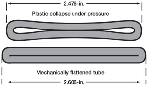
In the context of pressure service level ratings, a distinction is made between the PSC 3 and PSC 4 categories with respect to the design of the CT string, material yield strength and type of material used to construct the string. The predicted bend-cycle fatigue service life, along with the anticipated changes in the tube OD and wall thickness(es) resulting from diametral growth, must be considered when evaluating the expected performance of the well control stack component functions and pressure sealing capabilities. The surface piping recommendations for the PSC 3 and 4 categories are similar to the configuration offered for PSC 2 operations, but with a minimum working pressure rating of 15,000 psig. The dual-choke manifold should be remotely operated using hydraulic actuators, and a separate pressure recorder should be used to record pump and choke pressures independent of the CT unit. For any service in which MASP exceeds 7,500 psig, blind / shear combi-rams should be included in the well control stack riser assembly as a rule. In addition, a second high-pressure pump also should be incorporated as a backup pump or emergency kill pump. Bottomhole Assembly Components In the design of any CT well intervention service, the bottomhole assembly (BHA) components need to be selected based on performance for the intended service. The functions of CT BHA components used in underbalanced wellbore environments provide additional pressure safety features to protect the CT string and should be construed as fundamental to well control. The basic components that should be incorporated in all CT well control BHAs include connector, pressure check valve(s) and a type of fluids dispersion nozzle as discussed below. The CT connector selected must provide all needed mechanical load and pressure-containment functions projected for the prescribed service. As such, the connector must be capable of mechanically securing the BHA components to the CT string within the axial load limits expected for the prescribed service. In addition, the connector must also be capable of providing pressure isolation between the CT body and the connector to the MASP of the wellbore. In all underbalanced pressure environments, a pressure check valve component is considered to be a critical well control device and should always be incorporated in the BHA. The pressure check valve serves to restrict or severely reduce flow from the wellbore into the CT string should the tubing string experience a loss of internal pressure due to mechanical failure above the well control stack. As such, the pressure check valve is typically installed immediately below the CT connector. These pressure check valves may be designed as ball- or flapper-type, and may be run as a single valve or as tandem valves within a single housing. The fluid dispersion nozzle is typically selected based on the downhole hydrodynamic action desired. In some CT services, a multi-port dispersion nozzle may be omitted if downhole hydraulic energy is not a key performance issue. However, when conducting well control operations, the fluid dispersion nozzle generates a hydrodynamic fluid plume within the wellbore, which ensures localized dispersion of kill fluids, with minimum intermixing of resident fluids. For prudent well control operations, the fluid dispersion nozzle should be designed with multi-port jets that are capable of focusing the exiting fluid streams to contact the ID boundaries of the wellbore tubulars while minimizing frictional pressure loss. Selection of CT Size In general, CT size for the prescribed service is determined by the allowable clearances between the tube OD and the minimum restrictions within the wellbore, coupled with the need to achieve a specified fluids pumping rate. Further CT size may be dictated by logistical concerns for the total reel transport weight, with respect to crane load limits or weight restrictions for overland transport. One additional concern that should be included in CT size selection analysis is the maximum width dimension of the CT body, should plastic collapse occur. In cases where non-uniform loading on the CT body causes the tube to collapse on only one side, a slight dimensional distortion of the original tube diameter will occur. However, when a tube experiences complete plastic collapse, the tube walls are flattened together, with the outside boundary edges of the flattened tube specimen retaining a slightly-rounded shape. When evaluating CT OD sizes for a prescribed service, the maximum collapse width of the tube should not exceed the ID of the smallest restriction in the given completion tubing. This dimensional check ensures that, should a collapse event occur, the increased tube width will not cause the body to become jammed within the completion tubulars, restricting movement of the CT within the production tubing. The maximum width of the collapsed tube body also provides an estimate of annular clearance available between the collapsed tube and hole ID. Of equal concern is the maximum flattened width of the tube with respect to the proper function of the shear blades when an emergency separation of the collapsed tube body is required. For this analysis, the maximum collapsed width of the tube body should be compared to the effective cutting surface length on the shear blades installed within the primary well control stack (typically sized for the respective tube OD). If the maximum collapse width of the tube exceeds the effective cutting surface length of the shear blade, the outside edges of the blade will be mechanically loaded against the flattened tube body, leading to possible blade breakage and/or incomplete shear of the tube body. In this situation, it is recommended that a combination blind / shear ram, equipped with blades having sufficient cutting surface length, be installed within the riser. To assist this evaluation, the maximum width (Wmax) of a collapsed tube may be predicted using Eq. 2, in which original tube OD size (DC, in.) and actual wall thickness (t, in.) dimensions are known. Note that for a given tube OD, the maximum collapsed width will decrease with increasing wall thickness. The maximum width value calculated using Eq. 2 was found to be consistent with measurements of mechanically flattened tube specimens. However, in comparison to pressure-collapsed tube specimens, the maximum width of these tube specimens ranged from 93% to 98% of the mechanically flattened width, due to retained curvature at the edges of the OD surface, Fig. 5. When predicting the width of a pressure-induced, plastically collapsed tube body, a factor of 0.95 applied to the maximum flattened width value calculated in Eq. 2 should yield close agreement with the dimension of the collapse sample. The predicted values for maximum flattened width and plastically collapsed width are seen in Table 2 for specific CT sizes having a DC/t ratio between 13 and 14.
Condition of CT and Remaining Service Life Once the
appropriate CT size for the prescribed job has been determined, an
evaluation of the service history with predictions of remaining string
bend-cycle service life should be performed to assess "fitness-for-service."
This analysis of the CT string should incorporate model predictions
for accumulated fatigue-cycle damage, as well as de-rating factors for
internal and external surface corrosion and mechanical damage. The
prediction for remaining string service life must project the expected
manipulation of the tubing string within the wellbore when deployed
and retrieved at the proposed pumping pressures, and retain acceptable
life through-out the entire service program. Bibliography 1 World Oil’s Coiled Tubing Handbook, 3rd Edition, Gulf Publishing Company, Houston, TX, 1998. 2 American Petroleum Institute, Recommended Practice for Coiled Tubing Operations in Oil and Gas Well Services, API RP 5C7, First Edition, December, 1996. 3 Sas-Jaworsky, A., Practical Considerations for Enhancing Coiled Tubing Well Control Operations, SPE paper 60739, SPE/ICoTA Coiled Tubing Roundtable, Houston, Texas, April 5 – 6, 2000. 4 McCain, W. D. Jr., The Properties of Petroleum Fluids, The Petroleum Publishing Co., Tulsa, OK, 1973. 5 Sas-Jaworsky, A., "New guidelines should enhance coiled tubing well control security," World Oil, December, 1998.
|
|||||||||||||||||||||||||||||||||||||||||||||||||||||||||||||||||||||||||||||||||||||||||||||||||||||||||||||||||||||||||||||