Optimizing circulation while drilling underbalanced
WELL CONTROLOptimizing circulation while drilling underbalancedNew computer program allows hydraulic design of underbalanced drilling system to predict optimum circulating flowrate for any type of fluid from gas to conventional mudShifeng Tian, George H. Medley and Charles R. Stone, Signa Engineering Corp., Houston, Texas
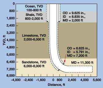
Conclusions developed in the discussion are that a comprehensive hydrodynamic model for underbalanced operations has been developed. Based on this new model, a computer program named Hydraulic UnderBalanced Simulator, or HUBS, has been developed to assist in design of underbalanced operations, especially in the process of optimizing underbalanced circulation rates. The new model is applicable to any drilling fluid, including gas, mist, foam, gasified (aerated) liquid, and conventional drilling mud. When designing an underbalanced operation, selection of underbalanced drilling fluids should be based primarily on formation pore pressure and the desired underbalanced condition inside the wellbore. Once proper fluids have been selected, the optimum circulation rate(s) for adequate hole cleaning can be determined using HUBS. Methods for determining the optimum circulation rate(s) are discussed. Optimum circulation rate(s) would provide sufficient hole-cleaning capacity while minimizing power and equipment requirements. Introduction The most important decisions involved in hydraulic design of an underbalanced drilling (UBD) operation include selection of drilling fluids and determination of circulation rates. These decisions determine whether the operation is underbalanced and how much underbalanced margin exists between fluid pressure in the wellbore and formation pressure, as well as hole-cleaning efficiency. Hole cleaning has significant effects on UBD efficiency. Hydraulic design also provides the basis for selection of pumps, compressors, fluid-handling equipment and other facilities. Hydraulic design is the key to success of an underbalanced operation. Although drilling-fluid type and circulation rate, together, determine the underbalanced condition in the wellbore – as well as hole-cleaning efficiency – each has a different degree of effect on these two requirements. Obviously, circulating-fluid density is the most important factor in achieving an underbalanced condition inside the wellbore, while hole-cleaning efficiency is mainly a function of circulation rate. In most cases, selection of a drilling fluid based on its density and formation pore pressure is much simpler than determining proper circulation rate. The main consideration in determining circulation rate is hole-cleaning efficiency. Generally, higher circulation rates provide better cleaning. Circulating insufficient drilling fluid causes cuttings accumulation inside the wellbore. This not only reduces drilling efficiency and creates downhole problems, it also increases fluid column weight in the annulus. The higher bottomhole pressure (BHP) caused by the heavier fluid column may result in an overbalanced condition in the wellbore. The accumulated cuttings could fall back to bottom, reducing drilling efficiency in a vertical well or forming a drill-cuttings bed in a horizontal well section. Conversely, circulating more fluid than needed will: increase frictional pressure loss along the flowpath, require higher pump capacity and increased fluid-handling equipment, consume unnecessary additional power and increase erosion of both the wellbore and drilling equipment by the high-speed cuttings. Ideally, UBD should operate at an optimum circulation rate which would provide sufficient hole cleaning, maintain an underbalanced condition in the wellbore, and minimize power and equipment requirements. Experiments have confirmed that a single, optimum circulation rate does not exist.1,2 Optimum circulation rate is affected by many factors such as wellbore / drillstring configuration, rate of penetration, cutting size and shape, rock density and drilling-fluid properties. To optimize underbalanced design, a Windows 98/95 style program named Hydraulic UnderBalanced Simulator, or HUBS, has been developed. One unique feature is its capability to predict optimum circulating flowrate for various drilling conditions. It is designed to handle any type of drilling fluid, including gas, mist, foam, gasified liquid and conventional mud. Past Attempts At Optimizing Circulation Rate Many attempts have been documented for determining circulation volume requirements for air, mist, foam and aerated-fluid drilling.3–9 Many of these studies focused on determining minimum volume requirement, or critical flowrate, rather than optimum circulation rate. The minimum volume requirement is based on the concept of particle terminal velocity. As Wolcott and Sharma9 stated, at a circulation flowrate above the critical value, drill cuttings will be delivered to the surface; below it, no cuttings will be delivered. The minimum volume requirement provides a lower boundary for selection of circulating rate with an open upper boundary. It cannot be used as a design tool to optimize underbalanced operation hydraulics. Ikoku et al.10 discussed the concept of optimum circulating rate for air drilling. Those authors believed that optimum conditions for air, mist or foam drilling are those that maximize penetration rate by lowering differential pressure at the bit, yet still have sufficient capacity to remove cuttings. Ikoku et al. did not present any model capable of predicting optimum injection rate. Instead, they presented a trial-and-error procedure for determining optimum air (gas)-injection rate at the drilling site. The procedure involves adjusting injection rate, measuring standpipe pressure and estimating BHP to obtain the relation between BHP and injection flowrate. This procedure cannot be used for design, since it can only be applied after drilling is underway. Supon and Adewumi10 did experimental work on conveying particles in vertical annuli. Their results not only confirmed the existence of an optimum circulating rate in air drilling, they also detected effects of mixed-size particles on pneumatic transportation. An important observation from their experiments is that the value of optimum circulating rate seems to be controlled by presence of coarse particles in the system. However, the value of the optimum circulating rate is not significantly affected by the amount of – i.e., the percentage of – coarse particles in the mixture. This observation is consistent with the modeling results of Tian and Adewumi.11 Hagar et al.2 published experimental results on conveying mixed-size particles in annuli, including the effects of annulus inclination. Results indicate that – if all other parameters are held constant – the value of optimum circulation rate increases with angle of inclination. Based on their experimental data, an empirical equation was created for predicting optimum circulating rate for air drilling. The equation indicates that the value of optimum circulating rate is dependent on rate of penetration, particle size and wellbore inclination angle. Tian and Adewumi11,12 developed a hydrodynamic model to predict optimum circulating rate for air drilling. Predicted results agree well with Supon and Adewumi’s experimental data. Parametric studies using the model indicate that optimum circulation rate is affected by many factors such as drilling speed, cutting size and shape, rock density and wellbore / drillstring configuration.13,14 The effect of wellbore inclination on optimum circulation rate was not included in the study. Based on the model, a general procedure for optimal design of air drilling hydraulics was created. Current Work, Special Features Of Hubs Extending the previous work of Tian and Adewumi,11–14 a comprehensive hydrodynamic model for underbalanced operations has been developed. Based on this new model, HUBS has been created to assist in the design of underbalanced operations, especially in the process of optimizing underbalanced circulation rates. The new model is applicable to any drilling fluid, including gas, mist, foam, gasified liquid and conventional drilling mud. Many special features were included, and some are outlined below. Modeling of six phases. During a UBD operation, both liquid and gas may be injected into the well as circulating fluids. Due to the underbalanced condition inside the wellbore, formation liquids (oil and water) and gas can flow into the wellbore. In addition, solid particles (cuttings) are also flowing with these fluids in the wellbore annulus. The new model treats each fluid – as well as solid particles – as an individual phase and is capable of handling up to six co-existing phases: injection liquid, injection gas, formation water, formation oil, formation gas and solid particles. Due to the difference in hydraulic properties (density, viscosity and compressibility) among these phases, they do not flow at the same speed. Because of slippage between phases, the mixture density of these fluids is dependent not only on density and flowrate of each phase, but also on the local velocity of each phase. Slippage between phases also causes additional pressure loss along the flowpath. Considering that hydraulic properties among all gas phases are relatively close compared to those of solid or liquid phases, the model assumes that injection gas and formation gas flow at the same speed. For the same reason, injection liquid and formation liquids also are assumed to flow at the same speed in the wellbore annulus. These assumptions not only speed up the numerical calculations, they also simplify flow-pattern solutions. Flow pattern of two-phase flow. Experiments have demonstrated that various flow patterns (bubble, slug, wavy, annular, etc.) exist in gas-liquid, two-phase flow. Flow patterns have significant effects on liquid holdup, hence mixture density, as well as frictional pressure loss. Therefore, it is important that the correct flow pattern be identified before mixture density and pressure loss can be calculated. Several correlations were developed, based on experimental data, to predict flow patterns for a given gas-liquid flow system. However, no study of flow patterns for three-phase flow (liquid-gas-solid particles) can be found in the literature. As several authors have pointed out that the solid volume fraction should not exceed 4–5% during normal drilling, the new model assumes that the two-phase flow correlation is valid with a small amount of solid particles in the system. The Beggs-Brill method15 was incorporated in the model for predicting flow patterns inside the drillstring, as well as in the wellbore annulus. The transportation of solid particles is based on drag forces exerted by the liquid-gas mixture. Flow patterns have significant effects on the efficiency of cutting transportation. Phase change between liquid and gas. Phase change between liquid and gas phases can occur during an underbalanced operation. Because of the underbalanced condition in the wellbore, formation fluids can continuously flow into the wellbore during an underbalanced operation. As formation fluids mixed with circulation fluids flow toward surface, dissolved gas may vaporize from liquid hydrocarbons, or liquid hydrocarbons can condense from natural gas, depending on local pressure and temperature in the wellbore. This is especially important in offshore drilling, where a wide range of pressures and temperatures exist inside the wellbore. Phase change would alter the ratio of liquid and gas phases in the wellbore, as well as their properties. This could have significant effect on: the flow pattern, both gravity and frictional pressure loss, and cuttings-carrying capacity of circulating fluids. Two widely used phase-equilibrium methods – the standard- flash- calculation and gas- solubility method – were incorporated into the model. The standard flash-calculation method has been widely used for gas-condensate systems, while the gas-solubility method was widely used for dissolved gas vaporizing from liquid hydrocarbons. HUBS also provides the user with the option to include injection fluids in the phase equilibrium calculation. This option is very useful if natural gas or oil-based liquids are included as circulation fluids. Two-phase flow through bit nozzles. Analytical equations for single-phase liquid or gas flow passing through restrictions have often been applied to bit-nozzle calculations. These equations are derived based on energy balance principles. The general assumptions involved in the derivations are: 1) change in pressure due to a change in elevation is negligible, 2) frictional pressure loss across the nozzles is negligible, 3) pressure drop across all of the nozzles is the same, 4) kinetic energy of the fluid above the nozzle is negligible, and 5) no heat exchange occurs between the fluid and the nozzles. During the derivation, liquid passing through bit nozzles is treated as incompressible fluid, while gas is a compressible fluid. The new model adds the additional assumption that no heat exchange and no phase change between liquid and gas occurs when passing through bit nozzles. Based on all these assumptions, a general bit-nozzle equation for liquid-gas, two-phase flow was derived. This new bit-nozzle equation was incorporated into HUBS. The advantage of the new nozzle equation is that it converges to the existing, single-phase, bit-nozzle equations if flowrate of one of the phases becomes zero. Parasite string and jet sub. Parasite strings (both attached tubing and concentric casing) and jet subs are sometimes used in underbalanced operations. A parasite string is a small-diameter tubing attached to the outer diameter of an existing casing. It is used to inject additional circulating fluids into the wellbore annulus at a specific location and does not alter configuration of the main circulation path. Concentric parasite casing is a temporary casing string run into the wellbore annulus to create an extra annulus between the temporary casing and an existing casing. Additional fluid is injected through the extra annulus and returns – together with the normal circulating fluids – through the annulus between the temporary casing and the drillstring. HUBS handles both parasite string types. It automatically reconfigures the annular flowpath when a concentric parasite casing is installed. A jet sub is used to bypass a portion of the circulating fluid from the drillstring into the wellbore annulus above the bit. The user specifies size and location of the jet sub. The newly derived, general, two-phase equation for bit nozzles (discussed above) is also used for jet-sub calculations. Jet-sub calculations require additional iterations to satisfy mass and energy balance. It should be noted that an improperly designed jet sub may cause hole-cleaning problems below the jet sub. HUBS will output a warning message when circulating flowrate is too small to lift cuttings at any location along the wellbore. Formation influx and lost circulation. Producing while drilling occurs during underbalanced operations. The amount of production is dependent on reservoir characteristics, as well as pressure difference between wellbore and formation pore pressures. Considering that only short-term production (a relatively small amount) is involved during an underbalanced operation, only a steady-state production model is incorporated into HUBS – i.e., average formation pore pressure is not affected by production during drilling. The production zone is divided into several sections along the wellbore, depending on total thickness. Production rate is calculated for each section using average pressure of that section. For an exploration well, reservoir properties may not be available at the time of the well design. HUBS provides an option for the user to input an estimated formation influx rate. In this case, influx rate is assumed to be evenly distributed along the total production-zone thickness, regardless of pressure difference between well and formation. Lost circulation during an overbalanced condition can also be modeled. The calculation method used is similar to that of formation influx. However, formation influx may cause a change in rheological properties of the circulating fluids, depending on what formation fluids and how much influx is coming into the wellbore. Lost circulation only reduces the circulation rate inside the wellbore annulus, without altering its rheological properties. Discussion And Examples Fig. 1 shows the wellbore configuration used for the calculations discussed in this article. It is an offshore well. Surface casing, 9-5/8 in., was set to a depth of 2,000 ft, and intermediate casing, 6-5/8 in., was set at 7,200 ft MD (6,953 ft TVD). Nearly 4,000 ft of horizontal section was drilled in a sandstone formation, with a penetration rate of 60 ft/hr.
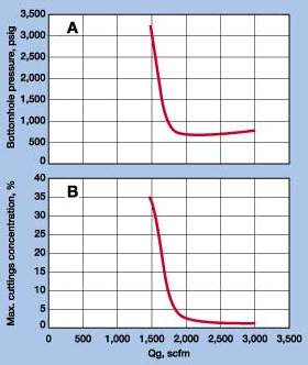
Results with nitrogen drilling. Figs. 2A and B show results calculated from HUBS using nitrogen as the circulation fluid. Fig. 2A shows the relation between BHP and nitrogen circulation rate. The shape of the curve is typical in air drilling and has been confirmed previously.1,2 The characteristic shape of the curve includes a minimum BHP and a much-steeper slope of the left side. The circulating flowrate corresponding to minimum BHP is the optimum flowrate, which provides sufficient hole-cleaning capacity while minimizing power and equipment requirements at the same time. Any circulating rate above or below optimum results in a higher BHP pressure.
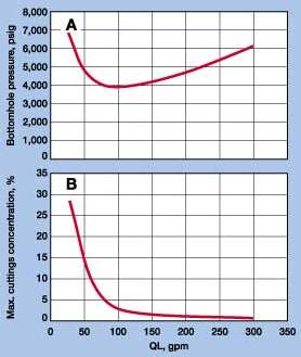
Fig. 2B shows that maximum cuttings concentration in the annulus decreases with increasing circulating rate. Cuttings concentration (or cutting volume fraction) varies along the wellbore. Maximum concentration may not always happen at the bottom of the well. It can occur at any place where annulus size is suddenly enlarged – such as above the drill collar or entering a larger well section from a smaller one. The results in Figs. 2A and B can be divided into two cuttings-transportation regions by the optimum circulating flowrate, about 2,000 scfm. On the right side of the optimum flowrate – any flowrate greater than the optimum point – effective hole cleaning is achieved. Circulating fluid in this region has enough cuttings-carrying capacity to clean the hole, and the cuttings are very dilute inside the wellbore. Fig. 2A shows that, in the effective hole-cleaning region, BHP increase with increasing flowrate is very slow compared to the region on the left side of optimum. Pressure increase in this region is mainly caused by frictional pressure loss. On the contrary, when circulation rate is below optimum (the left-side region), BHP increases sharply as flowrate decreases. In this region, the circulating fluid does not have enough energy to efficiently clean the hole, and cuttings start to accumulate inside the wellbore. The sharp BHP increase accompanying the flowrate decrease results from the sharp increase in fluid-column density in the annulus due to cuttings accumulation. Fig. 2B shows that, when circulating rate is greater than optimum, the well is efficiently cleaned, and the maximum cutting concentration inside the wellbore is below 3% by volume. In this region, further increasing circulating flowrate does not significantly improve hole cleaning, since change in maximum cuttings concentration is very small. Circulating more fluid than needed will result in increased frictional pressure loss along the flowpath, requiring higher pump capacity and increased fluid-handling equipment, consuming unnecessary additional power and increasing erosion of both wellbore and drilling equipment due to high cuttings velocity. Conversely, circulating insufficient drilling fluid causes cuttings accumulation inside the wellbore. This also sharply increases BHP (left side of the curve in Fig. 2A). This operating region should be avoided, since the insufficient hole-cleaning condition creates additional problems. The sharply-increased BHP may result in an overbalanced condition in the wellbore. Accumulated cuttings could fall back to bottom, reducing drilling efficiency in a vertical well or forming a cuttings bed in a horizontal well section. Using other circulating fluids. The concept of optimum flowrate is applicable to any drilling fluid, including mud drilling. Figs. 3A and B show results of using an 8.6-ppg polymer mud as circulating fluid in the same well. A minimum BHP of about 4,000 psig is apparent on the curve in Fig. 3A. The corresponding optimum circulation rate is about 100 gpm.
TVD of the horizontal well section is 7,183 ft. Static pressure exerted by the polymer fluid column can be calculated as 0.052 ´ 8.6 ´ 7,183 = 3,212 psig. From Fig. 3A, BHP at optimum circulation rate is about 4,000 psig. This indicates that, drilling with a liquid circulating fluid at the optimum circulation rate, about 80% of BHP is caused by the liquid column, while cuttings particles and frictional pressure losses together contribute the remaining 20%. Therefore, when liquid is used as circulation fluid, its density is the key factor in determining the underbalanced condition. It is interesting to note that maximum cuttings concentration corresponding to optimum circulation rate in both nitrogen and polymer drilling cases is about 3%. This is consistent with field experience that to drill a trouble-free well requires cuttings concentrations inside the wellbore to be kept below 4 to 5%. From Fig. 2A, BHP at the optimum circulation rate is about 700 psig when drilling with nitrogen as the circulating fluid. From Fig. 3A, BHP at the optimum circulation rate is about 4,000 psig when drilling with polymer. Theoretically, if both nitrogen and polymer are used together as circulating fluid, a BHP between 700 psig and 4,000 psig could be achieved, depending on the mix ratio. HUBS provides two options for handling mixtures of gas and liquid: two-phase flow modeling and foam flow modeling. The two-phase flow model incorporates the Beggs-Brill method15 for predicting gas-liquid flow patterns as well as the two-phase flow friction factor. The two-phase flow model is designed to handle mist and aerated or gasified fluid drilling. The foam flow model is derived based on Shanghani and Ikoku’s experimental data.16 Optimum circulation rate for mixed fluids. Determination of optimum circulation rate for a liquid and gas mixture is much more complicated than for single-phase flow, since there are numerous combinations of liquid and gas injection rates. Figs. 4 and 5 show calculated results for various combinations of gas and liquid injection ratios.
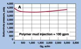
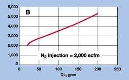
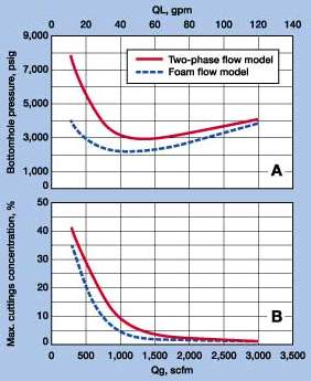
Fig. 4A shows BHP vs. gas flowrate while liquid injection is fixed at 100 gpm – optimum circulation rate when using only polymer mud as the circulating fluid. This curve also displays a minimum BHP. However, in this case, the flowrate corresponding to the minimum BHP is not the optimum circulation rate as discussed above. Since polymer mud at 100 gpm already has enough capacity to clean the hole, the addition of nitrogen to the circulating system does not significantly improve hole-cleaning efficiency. In fact, maximum cuttings concentrations corresponding to all cases in Fig. 4A are below 3%. BHP decrease with increase of nitrogen on the left side of the curve is mainly caused by reduction in mixture density (more nitrogen mixed with polymer mud). As more nitrogen is injected with the 100-gpm polymer liquid, fluid column weight inside the wellbore continues to decrease. At the same time, frictional pressure loss continues to increase, because more mass is flowing through the wellbore. On the right side of the curve, BHP increases with nitrogen flowrate, indicating frictional pressure loss outweighs the gravity pressure loss. Injecting polymer liquid at any fixed rate above optimum circulation rate (100 gpm) with various nitrogen injection rates would give a similar curve as the one shown in Fig. 4A. However, if polymer liquid is injected at a fixed rate below optimum circulation rate, addition of nitrogen does help clean the hole. There will be an optimum nitrogen injection rate that provides sufficient hole-cleaning capacity. However, this optimum circulation rate may not provide the required underbalanced condition inside the wellbore, since the liquid and gas injection ratio may not be the desired value. Fig. 4B shows BHP vs. polymer mud flowrate when nitrogen rate is fixed at 2,000 scfm (optimum circulation rate when using only nitrogen as circulation fluid). In this case, BHP increases with polymer injection rate. Nitrogen flowing at 2,000 scfm has sufficient energy to clean the hole. Therefore, addition of polymer to the circulating system does not significantly improve hole-cleaning efficiency, but it does affect BHP. The addition of polymer mud not only increases fluid column weight inside the well, it also causes more friction loss. This results in a fast BHP increase, as shown in Fig. 4B. This may be a good method to adjust the underbalanced condition inside the wellbore. However, it does not minimize the requirement for pumping- and fluid-handling equipment. Two-phase / foam flow models. A better way to determine optimum circulation rate, when using both liquid and gas as drilling fluid, is first to select the injection ratio of the liquid and gas based on the required underbalanced condition inside the wellbore. HUBS provides the option of designing optimum circulation rates with any liquid and gas injection ratio. For foam drilling, selecting a proper injection ratio is especially important, since foam quality (gas volume fraction) has significant effect on rheological properties. Figs. 5A and B show output results from HUBS using the two-phase flow model, as well as the foam-flow model. For comparison, the gas / liquid injection ratio for both cases was fixed at 25 scfm/gpm. Fig. 5A shows BHP vs. polymer and nitrogen circulation rates, while Fig. 5B displays maximum cuttings concentration vs. circulation rates.
Fig. 5A shows that the foam-flow model results in a slightly-smaller optimum circulating rate than that of the two-phase model. This is not surprising, since foam generally has a better cuttings-carrying capacity than nonfoamed fluid having the same gas / liquid ratio. When circulation rate is above the optimum point (on the right side of the curves), fluids in both cases have sufficient energy to transport the cuttings. Therefore, foam drilling may not provide much advantage over non-foam. This is illustrated in Fig. 5B. Maximum cuttings concentrations for both cases are very close to each other on the right sides of the curves. While foam does not provide much advantage over nonfoam fluids when circulating at a rate above the optimum point, it does generate a smaller BHP, Fig. 5A. Foam generally has a higher viscosity, which would result in higher frictional pressure loss. However, foam structure is able to bond liquid and gas, allowing them to flow at the same speed. In the nonfoam case, gas flows much faster than the liquid due to its light density and low viscosity. This results in a higher liquid holdup, hence a heavier fluid column inside the wellbore annulus. The lower BHP created by foam drilling indicates that gravity is the dominant factor inside the wellbore within the calculation range. Foam does show a better cuttings-carrying capability when circulation rate is below optimum. The left sides of the curves in Figs. 5A and B show that foam provides a less sharp increase in both BHP and maximum cuttings concentration as circulation rate decreases. If we set a maximum 3% of cuttings concentration as the criterion to determine circulation rate, the required injection rate for foam is much smaller than that for the nonfoam case, Fig. 5B. Figs. 5A and B show that, when circulation rate is below optimum, there will be less cuttings accumulation inside the wellbore – hence a lower BHP – when using foam as the circulation fluid than when using the same amount of liquid and gas without forming foam. This article was prepared from, and represents, the complete paper of the same
title written by the authors for presentation at the IADC Underbalanced Drilling Conference and Exhibition,
The Hague, the Netherlands, Oct. 27–28, 1999.
Literature Cited
The authors
|
 Shifeng
Tian, a senior research engineer at Signa Engineering Corp., Houston, received his BS degree in ME, an MS
in drilling engineering from China University of Geosciences and a PhD in petroleum and natural gas
engineering from The Pennsylvania State University. His research interests are multiphase flow modeling,
engineering optimization and software development. Before joining Signa, he worked at Maurer Engineering,
Inc., as a senior engineer for three years and at The Pennsylvania State University as a research associate
for four years.
Shifeng
Tian, a senior research engineer at Signa Engineering Corp., Houston, received his BS degree in ME, an MS
in drilling engineering from China University of Geosciences and a PhD in petroleum and natural gas
engineering from The Pennsylvania State University. His research interests are multiphase flow modeling,
engineering optimization and software development. Before joining Signa, he worked at Maurer Engineering,
Inc., as a senior engineer for three years and at The Pennsylvania State University as a research associate
for four years.  George
H. Medley, senior vice president of Engineering Research and Training with Signa Engineering Corp.,
Houston, holds a BS degree in civil engineering from Texas A&M University. He worked 17 years for Exxon in
reservoir, production and drilling engineering, and four years for Maurer Engineering as senior drilling
engineer. He has been the technical representative to the Drilling and Completions Committee of the DeepStar
consortium since 1996.
George
H. Medley, senior vice president of Engineering Research and Training with Signa Engineering Corp.,
Houston, holds a BS degree in civil engineering from Texas A&M University. He worked 17 years for Exxon in
reservoir, production and drilling engineering, and four years for Maurer Engineering as senior drilling
engineer. He has been the technical representative to the Drilling and Completions Committee of the DeepStar
consortium since 1996.  Charles
R. "Rick" Stone, chairman / CEO of Signa Engineering Corp., Houston, earned a BS in ME from
Texas A&M University in 1979. He has 21 years’ experience in oil and gas operations. He is a
registered professional engineer in Texas. He has been active with the SPE and served as a distinguished
lecturer for horizontal underbalanced drilling in 1993 and 1994.
Charles
R. "Rick" Stone, chairman / CEO of Signa Engineering Corp., Houston, earned a BS in ME from
Texas A&M University in 1979. He has 21 years’ experience in oil and gas operations. He is a
registered professional engineer in Texas. He has been active with the SPE and served as a distinguished
lecturer for horizontal underbalanced drilling in 1993 and 1994.
