Deepwater challenges generate new industry design concepts
OFFSHORE REPORTDeepwater challenges generate new industry design conceptsRecently introduced technologies give offshore operators added options for solving operational and economic problems
These new technologies include:
Deepwater drilling / production system offers low cost / versatilityPercy J. Freeman, Jr., P. E., Program manager, MinDOC, LLC Oil companies have moved very cautiously into deep water with their production facilities. Limited basic technology was the first problem, but that was quickly solved. Early solutions, however, were expensive and could only be justified for very large fields. As deepwater technology improves efficiency, it must be kept in mind that the number of large "elephant" fields to be discovered will certainly diminish. And so the routine continues. Technological advances lower the minimal reserve threshold for oil companies. However, with each new deepwater production system, there usually come other limitations, e.g.: "It’s a good system, but it can’t accommodate dry trees." "It’s extremely stable, but it can’t go beyond 3,500 ft of water." Or, "An efficient system as long as the payload is under 4,000 t." Described here is a deepwater drilling / production system that is applicable across the full spectrum of water depths and payloads expected for the next decade and beyond. The MinDOC Deepwater Drilling / Production System offers facilities with low motions, low capital expense, and versatility to: 1) increase or decrease the number of wells without significantly impacting costs, 2) increase payload capacity of an existing hull by as much as 100%, or more, 3) plan for payload growth without "killing project economics," and 4) relocate the structure to a new field without removing existing topsides. Four companies are active in the development of MinDOC: 1) Gulf Island Fabrication, Inc., Houma, Louisiana, provides fabrication / constructability expertise; 2) W. H. Linder & Assoc. and W. S. Nelson & Co. – known as the Deepwater Consulting Alliance (DCA) – provides process facilities and project management expertise; 3) Bennett & Associates provides naval architecture expertise; and 4) Reading & Bates Development Co., a subsidiary of RB Falcon, contributes drilling, riser and mooring technology.
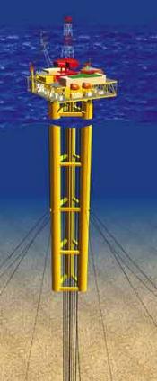
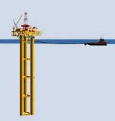
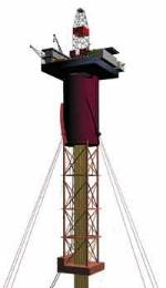
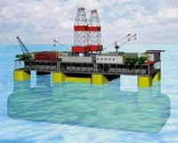
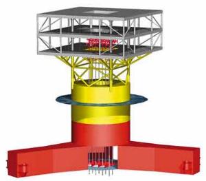
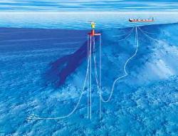
One contracted study has been completed for Texaco, and the developers are working on three new studies. The system is presently being considered for a project in 2,200-ft water in the U.S. Gulf of Mexico. System description. The system consists of a hull, moorings, topsides process facilities, drilling / workover rig and production / export risers, Fig. 1. The typical hull comprises three vertical cylinders, or columns, arranged in a triangular pattern. Each column is about 700 ft in length. Column diameters will vary, depending on specific payload or operational requirements. The columns are joined at horizontal levels by box girders. Columns have interior ring frames spaced at 10-ft vertical intervals throughout their entire length. Box girders are conventionally tee-stiffened. The semi-taut mooring system will comprise either nine or 12 lines. These can be primarily wire or fiber. Either suction piles or driven piles provide seabed anchorage. The mooring system will be installed using anchor handling tugs and crews; no derrick barge will be required for mooring system installation. Stability is provided by seawater and/or high-density ballast (HDB). Varying the amount of HDB can change the payload capacity of any given hull size. Trim stability is controlled with seawater ballast. In the topsides area, facilities can be minimal to very large, and anywhere in between. A drilling rig can be accommodated in any size from a small workover to a full platform rig. Production input can come from dry trees, from flowlines tied back from subsea completions, or from import lines from other fields. Production risers can be either top-tensioned or self-buoyant type. Import or export lines will be steel catenary risers. Motions: The key to performance. Following the conclusion of favorable analytical exercises to approximate motion characteristics of the hull, the decision was made to proceed with a model test to accurately ascertain motions. Seakeeping characteristics of a 1:105 scale model of the MinDOC were measured in the Maneuvering and Seakeeping (MASK) basin of the Naval Surface Warfare Center, Carderock Division. The platform was moored in the deep-trench area of the MASK to simulate mooring in more than 3,000 ft of water. The purpose of the experiment was to determine platform motions in various wave conditions. Motions in regular and large, irregular wave conditions – including conditions designed to model the seaway measured in the Gulf of Mexico during Hurricane Camille – were recorded for two mooring fairlead locations and at two relative wave headings. Natural periods of the hull for pitch and roll vary between 82 and 86 sec, depending on location of the fairleads; heave natural period is 29 sec. Both of these fall well outside the range of typical Gulf of Mexico predominant wave periods and are indicative of the low motions experienced by the system’s hull. Results of the model test reinforced the belief that the hull motions are indeed the lowest of any nontethered floating system on the market today. With good heave and pitch / roll characteristics, riser systems will be less expensive and more reliable. Low CAPEX: The key to AFE approval. The hull and moorings of the new system have been developed with the goal of achieving lowest possible CAPEX. With this in mind, Gulf Island Fabrication had an integral function in the design process. The result is a hull structure that comprises only two modular sections, cylinders and boxes. It is very repetitious and, therefore, lends itself to "assembly line" type construction. And even though it may look somewhat different, the hull can be fabricated by any qualified jacket fabricator. Ease of loadout and transport to the site further enhances the CAPEX picture. After assembly in the yard, the hull is winched onto a barge in the same fashion that a jacket is loaded out on skidways. Once on the barge, the hull can be floated off the barge at the appropriate location (either at dockside or at a location offshore). The barge is submerged and the hull floats off on two columns. The barge, it should be noted, is only a means of getting the hull floating on two columns. If the hull is erected in a drydock, the facility can be flooded and the hull never needs to be put on a barge. Once floating, the hull will tow easily to the site. Upon arrival, one of the waterline columns will be flooded to leave the remaining two columns on the surface. The lower section of these two columns would then be free-flooded, and the structure would slowly upend itself (much like a conventional jacket upending). No derrick barge is required for the entire hull installation. Topsides installation can be undertaken with or without assistance of a derrick barge. The MinDOC hull and topsides have been tailored to facilitate topsides floatover. Notwithstanding savings in derrick barge time, significant savings can be realized in hookup and commissioning costs, as well. Design versatility: The key to first-use optimization. The hull design was originally intended to carry lighter payloads associated with more-marginal facilities. The hull is, however, an extremely scalable design concept. It turns out that it can be utilized for payloads ranging from as little as 1,000 to as much as 60,000 t. The hull’s open architecture lends itself very well to optimization, not only of the number of wells, but also the configuration. Spacing of the columns can be varied to suit the desired number and layout of wells. This will improve design of the drilling rig and ultimately increase operational efficiency. Operational versatility: The key to long-term utilization. Operational versatility is perhaps one of MinDOC’s greatest and, to date, least appreciated strengths. A hull capable of carrying a certain payload has that capability in water depths ranging from 1,500 to 10,000 ft of water – the only thing that changes is the mooring system and the riser tensioning system. This fact alone, however, would not be so significant if the hull could not be relocated easily. Ease of relocation is facilitated by the fact that it can be towed to its new location with the topsides in place, Fig. 2.
Payload versatility is yet another of the system’s significant attributes. Any given size of hull is capable of safely carrying a wide range of possible payloads. Payload capabilities are modified by changing the amount and type of ballast. For the lightest payloads, seawater alone is used. The heaviest payloads are carried by using a large amount of high-density ballast. The ability to accommodate "facility growth" provides reduced risk to operators in deep water. In conclusion, the new system offers operators a stable platform from which to
drill and/or produce, through utilization of existing riser and well systems. Its unique structure makes it
easier and relatively inexpensive to fabricate and install – and also easier to relocate after field
depletion. In short, the design solution has great applicability across a broad spectrum of both payloads and
water depths.
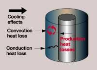
Completion fluid system aids continuous deepwater productionRick Pearcy and Dan Johnson, OSCA, Inc., Houston Well completion design and implementation are critical to assure the continuous, desired level of oil and/or gas production. Deepwater completions require specialized techniques, not only because of the requirement for maximum production to justify higher operating expenditures, but also the need to assure sustained production levels for an extended period of time, with minimal risks. As the offshore market moves toward deeper waters, the challenges become increasingly complicated. Major efforts associated with sustaining maximum production are being jeopardized because of problems associated with undesired depositional buildup in oil wells or formation of hydrates in gas wells. It has become apparent that these undesirable effects have, in part, been a result of the lack of natural, formation heat retention, compounded by the impact of deepwater cooling effects. A new product from OSCA, called InsulGel, has been developed and utilized to help sustain desired production levels. Heat transfer problems. Heat transfer occurs in all producing wells. Bottomhole temperatures (BHTs) are usually much higher than either surface or mudline temperatures, and the difference is a significant and continuous negative gradient up to the surface gathering systems. Produced hydrocarbons tend to lose temperature during production, sometimes causing problems as the gas or oil approaches a critical, lower temperature. Formation of gas hydrates, plugging caused by depositions, and precipitation of salts are all temperature-related phenomena. These problems can be especially significant in deepwater wells, where temperature differences are a constant, not only because of the economical impact due to loss of significant production, but also the inability to access the wellbore (intervention) in a timely manner. In addition to the possible problematic buildups or precipitants created from falling temperatures, heat transfer can also cause other problems or risks. Multiple casing strings are sometimes sealed in place when subsea trees are set, and the annuli between these strings cannot be vented of any pressure buildup. The transfer of heat into these annuli can increase temperatures, and therefore pressures, in the sealed space, leading to possible casing failure. All deepwater hydrocarbon producing wells have a BHT much higher than the mudline (seafloor) producing temperature. This temperature drop corresponds to a heat loss through and across the annular space between tubing and casing. The impact and problems, such as paraffin or asphaltene deposition, all relate to heat transfer events in the wellbore, making heat management a critical part of the completion operation. Heat from the production tubing can be lost, or transferred, to the outer casing annulus by several methods. However, two of the most prevalent are conduction and convection, Fig. 1.
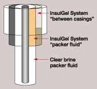
Thermal conductivity is a thermophysical property that relates to a substance’s ability to conduct heat. This property applies to liquids, solids and gases. The lower the thermal conductivity, the less heat transmission through the material, thus the more insulating it becomes. As a general rule, gases have much lower thermal conductivities than liquids, which are often lower than solids. In addition to thermal conductivity in a particular fluid, heat can be lost through convection currents set up in the annulus. The warm fluid nearest the tubing tends to rise, while cooler liquid nearest the casing falls, creating a physical liquid flow that circulates in the annulus. This circulation tends to more rapidly equalize temperature across the annular space, increasing heat loss to the casing side. Available solutions. Conventional packer fluids, such as inhibited clear-brine fluids, have less-than-desired conductivity values. To compensate for these limited values, operators try to retain the natural heat contained within the produced hydrocarbons by utilizing material such as vacuum-insulated tubing and syntactic foams. While the application of these mechanisms is sound, operators have searched for other alternatives because of associated costs and, sometimes, product availability. Even though conduction is a critical component for retaining natural properties of produced fluid(s), many believe that free convection through the annulus is the primary transfer mechanism by which the produced fluids lose heat. It has been suggested that convection may contribute up to 80% of the heat loss. Since convection is physical movement, steps that minimize or prevent fluid movement can reduce this effect. The intrinsic rheology of the annular fluid will determine the speed at which the fluid may circulate. Using more-viscous fluids can improve the insulating properties. The use of a specific fluid like the InsulGel system is designed to make the convection phenomenon less likely to occur and, thereby, reduce heat transfer through this mechanism. Other systems, like oil-based fluids, generally have lower conductivities than water-based systems, but can present problems with compatibility or environmental discharge. Water-based systems are more compatible with completion fluids and elastomers, and can have a much-lower toxicity profile. OSCA has found the conductivity of water can even be lowered by special blending of select brine solutions and combining other, unique components to help improve heat retention properties. In addition to heat retention within the produced hydrocarbons, another major concern has been the attempt to reduce excessive heat transfer to the adjoining annuli and beyond, Fig. 2. Many of these annuli, especially within a subsea application, are nonvented once the tree is set. The high temperatures can cause the fluids / muds within these sealed areas to heat and expand beyond the burst capacity of the casing. Placing an InsulGel-type system during the initial installation of this casing interval can reduce the heat transfer capacity and thereby prevent such expansion levels.
Application methods. The present situation requires that temperatures in the outer annuli be kept as low as possible. Currently, the most efficient way to accomplish this is to allow heat transfers within the lower section of the well, typically below the top of the cement in the adjacent outside casing. An inhibited packer fluid package is designed and placed in the bottom portion of the well, while the new gel system is placed in the annulus above this interval to allow maximum heat retention to surface. This method will allow naturally occurring convection effects to take place in the lower portion, while negative cooling effects around the mudline are addressed. While placement of the new gel system within an entire wellbore has been done, it has been determined that the fluid is most effective when placed in the top – say 3,500 to 7,000-ft – portion of the wellbore. Mixing and pumping of the insulating fluid system has been carefully engineered to complement the ongoing operations. The developer has designed and implemented the system with the ability to be mixed "on the fly" with its marine vessels and pumped into position within the wellbore. This method not only eliminates concerns associated with the pumping of a viscous material, it also eases any rig-handling or contamination concerns. Case history. Reading & Bates Development Co.’s Gyrfalcon project, a 15,000-psi subsea completion in the Gulf of Mexico, is a prime application example. The operator had limited choices in finding solutions to wax-deposition and hydrate-formation problems inside tubing during production, as well as high annular pressures due to heat loss from the wellbore. OSCA engineers designed, blended and pumped two separate InsulGel systems. Because of the unique design features of the subsea tree, studies were undertaken to review possible heat transfers into the initial external casing annuli and the thermal expansion effects. When modeling showed that conventional muds contained within this sealed area could possibly demonstrate thermal expansion coefficients greater than casing burst ratings, it became necessary to pursue an alternative system to alleviate possible failures. To help reduce the excessive thermal-expansion and heat-transfer values within the sealed area, the operations program was slightly altered to place the insulating fluid between the two casing strings. This particular project presented several unique approaches. One was engineering of a packer fluid system that would address not only the need to retain maximum heat coefficients, but also supply sufficient density requirements because of the higher-than-normal bottomhole pressures. The final stages of operations required the installation of high-density, inhibited packer fluid in the lower part of the wellbore, while the new insulating fluid system – at one pound-per-gallon less density – was placed in the upper portion of the wellbore. The total designed packer fluid system addressed not only the need for maximum heat retention at the subsea tree, but also all associated compatibility issues critical to deepwater completions, i.e., elastomers, control line fluids, metallurgy, etc. This is one example of a new technology being explored and applied by
operators to address the critical concern of continuous hydrocarbon production at desired levels. The new
insulating fluid system has been applied to nearly a dozen deepwater wells. Information gathering and further
testing are being conducted in an attempt to assure optimum oil and gas deliverability.
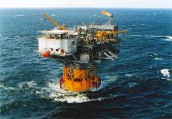
New designs for deepwater Spar and FPSOAker Maritime, Inc. has introduced designs for two new systems that can increase the efficiency and application of deepwater facilities for field developments. A result of ongoing R&D, the two new facility designs include a modified Spar applicable for waters to 10,000 ft, called the Truss Spar. The second, non-conventional FPSO concept is the AKER-DPS 2000, with drilling capabilities and 2-million-bbl storage. Highlights of the two new concepts are shown here. Advantages of new Spar design. The Spar concept as a floating vessel is now recognized as a reliable and economic option for developing deepwater offshore hydrocarbon reservoirs. The first three Spar platforms – Neptune, Genesis and Diana – were of the "classic" caisson Spar design. A new design, the Truss Spar, will offer even more advantages for deepwater developments. Kerr-McGee has chosen the Truss Spar for development of its Nansen field in the Gulf of Mexico.
With the new system, the cylindrical midsection of the Classic is replaced with a truss section very similar to the space frames used in conventional, bottom-founded fixed platforms. This truss section is considerably lighter than the equivalent cylindrical section of the Classic design, and thus will be less expensive to fabricate. Other, more-significant advantages can be attributed to the design. Since weight of the truss section is insensitive to width of the truss, the centerwell width (and Spar diameter) can be increased to accommodate additional risers with little cost penalty. This feature allows for the addition of spare well slots that can be used to take advantage of the upside potential of the reservoir to handle more wells. When this additional well count capability is coupled with the new Spar’s design that allows for expanding topside production equipment to handle additional throughput, the end result is an offshore production concept that will help operators control reservoir reserve risks. If the reservoir proves to be better than the most likely case, the system can be expanded to take advantage of this upside potential. If it proves to be worse than expected, the reservoir can be depleted rapidly and the Spar moved to a new site. In this case, much of the topside equipment and many of the riser components can be reused, helping the operator control downside risks. Many advantages of the new concept are attributed to the variety of riser systems that can be accommodated. Spar risers are shielded from surface wave and current actions, which reduces the potential for fatigue damage and riser interference. As a result, extreme-event stresses are easily accommodated, and fatigue damage and wear can be maintained well within allowable limits. Spar platforms can accommodate steel catenary risers (SCRs), which are relatively easy to install and less expensive than either top-tensioned, export / import risers or flexible catenary risers. The new design allows for the use of the simple, pull-tube concept for supporting the SCRs. The pull-tube approach allows easy installation of the SCR and results in a gently curving riser geometry that permits pipeline pigging and flowline coiled tubing operations. Deepwater FPSO with drilling capability. The AKER-DPS 2000 is a deepwater FPSO design that offers drilling and production capability, together with storage capacity for up to 2.0 million bbl of crude oil. The design is based on a phased-development approach whereby first oil is achieved in a shorter time than with other traditional alternatives, and timing of major expenditures is effectively integrated into overall field development cost.
Among the design’s features is its flexibility in construction, installation and operation. The hull is unique compared to other FPSOs due to its small water plane area, yet large storage capacity. It is constructed of steel and can be moored using conventional, semi-taut steel mooring lines in operating water depths up to 10,000 ft. A wet-oil storage system eliminates inert gas, and reduces hull scantlings and ballasting requirements. The topside comprises three pre-assembled units including oil processing, drilling and utility accommodations. These are built in one piece and may be floated onto the hull at site or in sheltered waters near fabrication sites. Offshore hookup and commissioning is minimized. Process units can be added as required, allowing flexibility in development options, shorter schedules and less risk. The design can accommodate two drilling units, which can be replaced by workover rigs later. The excellent seakeeping characteristics of the vessel allow simultaneous drilling from the two rigs, as well as workover, when required. Therefore, the cost of drilling and workover from a MODU is eliminated. The centerwell can hold 40 or more dry-tree wells and steel catenary risers from subsea wells. The drilling and dry-tree-production riser systems use proven Spar technology. These tree and riser systems are less expensive than the subsea tree and flowline, and provide easy access for workover from the FPSO. Also, a typical dry-tree well produces more oil from the reservoir than a subsea well. Designs are currently available for West Africa, Brazil and other equatorial
environments. Potential for use in the Gulf of Mexico is being evaluated.
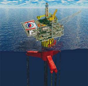
Expanded mono-hull TLP applicationsAtlantia Offshore Ltd., Houston, presently has two SeaStar TLPs operating in the Gulf of Mexico on British-Borneo’s Morpeth (1998) and Allegheny (1999) fields in 1,670 and 3,300-ft water depths, respectively. A third SeaStar TLP is under construction for Chevron / BHP’s Typhoon project in 2,100-ft water. These three projects represent the "wet-tree" concept, featuring subsea well completions tied back to the TLP for full processing and export. Two other versions of the proven mono-column-hull TLP – the SeaStar Surface Completion Platform and the SeaStar Utility Platform (MicroStar) – have also been designed to offer a wide range of deepwater applications, as will be described herein. Wet-tree SeaStar Production Platform. The three wet-tree TLPs to date have 58-ft-dia. hulls and three radial pontoons – each anchored to the seabed by neutrally-buoyant tubular steel tendons, Fig. 1.1,2 The tendons are latched into individual steel piles driven into the seabed. The substructure supports a two-level deck on a jacket-type structure. Unlike other TLPs, the deck structure of the mono-column TLP is not required to resist column interaction loads, thus minimizing weight.
A range of payloads can be supported by the wet-tree TLP – the maximum for the three existing projects being 5,000 short tons. Regarding sensitivity, the overall payload capacity of the mono-column TLP can be increased by adding a lower extension to the hull relatively late in the design. This gives an operator the ability to increase payload by as much as 25% after detail design has started for a given hull diameter. The wet-tree SeaStar typically would not support a drilling or workover completion rig. However, coiled tubing access from the platform down individual production flowlines is typical. Morpeth presently has three subsea wells and one water injector; Allegheny has five subsea wells and one spare. On the three wet-tree models, the bottom of the mono column is blanked off, thus sealing off the central moonpool to provide additional buoyancy. Subsea tiebacks and export lines access the deck via external risers. Details of the wet-tree systems are available in published literature.1 – 4 The developer has expanded the SeaStar Production Platform concept with two additional designs, as described below: 1) the SeaStar Surface Completion Platform, and 2) the SeaStar Utility Platform, or MicroStar. Surface Completion Platform. In this configuration, column diameter is increased to allow for larger payloads, and a central moonpool accommodates individual dry-tree production risers, Fig. 2. A drilling / workover rig is added for well intervention, along with full processing and oil/gas export facilities.
Alternative configurations of the surface completion TLP include a wellhead-only platform that accommodates full drilling / workover requirements. This configuration is often considered in conjunction with a host (FPSO) platform for full processing. The hull and production decks may be sized to provide adequate area and payload capacity, in excess of 18,000 tons (t), for the GOM environment. The system can also serve as a host for future subsea tiebacks. Catenary production risers can be added to the platform to accommodate such tiebacks. A key advantage of the SeaStar TLP concept is its favorable motion characteristics compared to laterally moored systems. Heave, roll and pitch of the platform are negligible. Coupled with use of a riser keel joint, the dry-tree production risers display very little differential motion between risers and platform, Fig. 3. As a result, riser-tensioning system cost is minimized, and interfaces between tree and manifold are simplified.
Atlantia model tested the surface-completion TLP in early 1999 at the Offshore Technology Research Center at Texas A&M University. The system was configured to support a 10,000-t payload and up to 18 wells. The test evaluated performance in 3,000 and 6,000-ft water, under 100-yr hurricane waves and 1,000-yr hurricane conditions. The model simulated a 90-ft-dia. hull. Recent designs have extended the hull size to accommodate even larger payloads. Utility Platform. The MicroStar TLP Platform is a system design that offers a low-cost solution to the problem of maintaining / supporting longer subsea-well tiebacks, Fig. 4.
This smaller version of the mono-column system can be placed near, or over, subsea wells to provide a not-normally-manned platform that can be used to: 1) launch pigs through long flowlines to the host platform (or FPSO), 2) store and inject chemicals, and 3) control and monitor wells. Cost advantages include elimination of long, non-reusable umbilicals to the host platform, and need for a second pipeline typically used for a pigging loop; and it allows for a direct hydraulic well control system. Further, the system has a residual value – it can be salvaged and redeployed. Range of application. In summary, the SeaStar configurations overviewed here, and modifications within these classifications, offer these basic applications / advantages:
For the Gulf of Mexico, the SeaStar TLP’s operating niche is up to
18,000-t payload – with enhanced stability from tension-leg mooring design – and up to 18 wells,
using a small moonpool. Conventional platforms (such as the TLP, FPS, Spar, Multi-Spar and FPSO), conversely,
can extend payloads to 30,000 t – with stability from hull design – and well numbers up to 30, using
larger moonpools. SeaStar’s design, thus, is practical for smaller payloads and fewer wells, where
economic development, flexibility and schedule may be critical to overall project success.
Literature Cited
|