Waterflood strategy evolves from improved 3-D flow unit characterization
Waterflood strategy evolves from improved 3-D flow unit characterizationDavid Boneau, Yates Petroleum Corp., Artesia, N.M.
Bottom line. A high-resolution, 3-D data set, combined with 3-D visualization tools, led Yates Petroleum to a new waterflooding strategy — design an individual waterflood for each identified major flow unit. For a pilot flood, the targeted flow unit will be flooded from the bottom to take advantage of vertical continuity, while reducing the impact of horizontal high permeability intervals. Field history. Dagger Draw field is located in Eddy County of southeastern New Mexico. It covers about 70 sq mi. Production is from vuggy carbonates of Canyon age ranging in depth from 7,500 to 8,000 ft. Reservoir porosity is believed to be associated with reef framework material that was dolomitized by connate waters moving through the primary porosity. To date, the field has produced 60 million bbl of oil and 275 Bcf of natural gas through primary recovery methods. However, total fluid volumes and reservoir pressure have been falling, which indicate that some parts of the field are nearing primary depletion. To counter this trend, Yates tried a conventional waterflood pilot with pattern injection wells. Rapid water breakthrough, without significant incremental oil, showed that this approach was unsatisfactory. A study of the reservoir was initiated by Yates, in cooperation with consulting firm The Scotia Group, to determine if well productivity could be tied to reservoir architecture and if this information could be used to design an improved oil recovery (IOR) strategy. 3-D porosity data volume. The study began with the construction of a detailed network of conventional maps and cross-sections. Regardless of evident correlations, no clear architecture could be derived that explained well performance. To improve the ability to examine and analyze the logs, a 3-D data set of porosity data was created from 160 well logs in an 18-sq-mi area. Generating the 3-D porosity data involved the selection of a stratigraphic datum on the top of the reef carbonate section. From that datum, log porosity values were extracted every five ft from the 350-ft-thick reservoir. For each of these five-ft intervals, or slices, log porosity values were gridded using a non-linear algorithm at an interval of one-tenth of the well spacing. When stacked, these layers comprise the 3-D porosity data set. This layer slicing process is akin to statistical sampling, in which the samples can approximate the whole reservoir. More details can be resolved if the slices are taken from closer intervals. Flow unit identification. The 3-D porosity data set was used to identify high storage and flow capacity portions (flow units) of the reservoir. The data were processed with a program that summarized rock properties and identified contiguous portions of the data set that met a minimum porosity. Other software programs were used to list which flow units occurred in each well, and to extract the 3-D data set for any specific flow unit. Although the location and dimensions of the flow units could be depicted using maps and cross-sections, their complex geometry prevented an accurate understanding of their shape. The visualization problem was overcome with the aid of advanced graphics algorithms. These algorithms provided the means to display the flow units in three dimensions, allowing their inspection from any angle. Well locations, borehole traces, and perforations added to these images aided in the reality check of the location of the flow units. They also helped identify uncompleted intervals and provided the means for identifying portions of the reservoir that might respond as a common vessel to pressure maintenance. Choosing the pilot area. The initial strategy was to locate the main flow units within the reservoir, then design an individual waterflood for each major flow unit. Using a 6% porosity cutoff, 216 flow units were identified. Only the two largest flow units were considered for the pilot flood, Fig. 1. The one that extends off Yates-controlled acreage was not chosen.
The area that was chosen for the pilot program is part of the second large flow unit. This area appears to have limited connectivity with the remainder of the flow unit and is somewhat limited in areal extent (about 800 acres). It also has a moderate pore volume that could be realistically flooded (23 million bbl of oil), with vertical continuity of over 150 ft, Fig. 2. There are several good wells in this flow unit that each have a cumulative recovery of over 500,000 bbl.
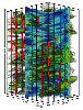
To design the pilot flood, 3-D visualization, as well as conventional engineering methods, were used. Fig. 3 is one perspective of the portion of the reservoir chosen for the pilot flood. This image involves the 2-D and 3-D contouring of the porosity data. The various components of this diagram helped identify where water might be injected and the anticipated flow path.
The failure of the prior pattern flood was attributed in part to high permeability pathways that caused poor reservoir sweep. For the new pilot, a bottom-up flood was conceived to take advantage of the vertical extent of the flow unit and lessen the impact of the mostly horizontal high permeability intervals. For the waterflood design, individual well log data were used to identify injection intervals and calculate injectivity. The construction and visualization of the 3-D data set produced from logs provided the means to identify portions of the reservoir that appear to have controlled productivity. The next step is to test these concepts in the field through the installation and diligent monitoring of the waterflood pilot. Value of 3-D data. The statistical approach to building the 3-D data volume has implications beyond Dagger Draw. The high resolution information provides a means to examine the architecture of the reservoir short of trying 3-D seismic, which likely will not image reservoir features at the scale that is required. The process is ideally suited for carbonate reservoirs that are fully developed but still too complex to describe with conventional methods. The accompanying images give an idea of the clarity and impact of the 3-D images. On a computer, these images can be rotated, zoomed and panned, allowing full inspection. Application to other reservoirs. Rapid and extreme changes in reservoir properties, as frequently experienced in carbonate reservoirs, make correlation and prediction of productive intervals nearly impossible. Inadequate reservoir characterization becomes evident when it comes time to waterflood, and injected water takes unpredictable paths or almost immediately breaks through. For Dagger Draw, improved reservoir characterization and a subsequent tailored waterflood strategy confirm the value of 3-D visualization. The improved reservoir descriptions can be used to identify recompletion opportunities, site horizontal wells and design IOR projects. Reservoir characterization studies like this Dagger Draw example can now be performed with much less investment in hardware, software and staff time in comparison to historical practices. Fields with 100 or more logs likely can be studied using these methods in a matter of weeks and for tens of thousands of dollars, as opposed to many months and hundreds of thousands of dollars for a conventional study. Such reservoir descriptions are now truly available to the average operator. The authorsDavid Boneau has worked as a reservoir engineer at Yates Petroleum in Artesia, N.M., for 18 years, and previously as a research and reservoir engineer at Phillips Petroleum for 12 years. He has experience with reservoir characterization and improved recovery in the Mid-Continent, Texas and Rocky Mountain areas. At Yates, he helped build the company’s engineering department and installed several waterfloods, a CO2 pilot flood, computer networks and engineering software. He is a member of PTTC’s Board of Directors. Patrick Lowry is a senior geologist with The Scotia Group in Dallas, where he has worked since 1996. He previously worked for the Keplinger Companies and as an independent geologist. He specializes in reservoir description, integrating core, petrophysical, seismic and production data. Lowry is particularly interested in using computer-based tools to assimilate reservoir data and numerical methods that aid in identifying and imaging reservoir components that control productivity. He holds a BS and an MS in geology from Arizona State University. Copyright © 1999 World
Oil |