Well
Control
How a snubbing unit was used to regain
control of a subsea well
Snubbing
equipment on a jackup, a specially fabricated high-pressure riser and
the original subsea BOPs were used to kill and plug a problem well
David A. Barnett, Engineering
Manager, Wild Well Control, Inc.; and D.C. Tyagi and A. K.
Mehra, Oil & Natural Gas Corp., Ltd.
Well B-24-2 was drilled in the Bombay
High region offshore India. Even though water depth was 266 ft, a
drillship was used for drilling since underlying soil instability in
the area might allow a “punch-through” if a bottom-supported
rig were used.
The well encountered a kick while
displacing mud prior to completion operations. Complications, which
arose while circulating the kick, made it necessary to shear the drill
pipe. Characteristics of the pressure influx path and other factors
created a situation in which further application of conventional well
control techniques was not advisable. A thorough evaluation of risks
versus the probability of success was carried out for several possible
control techniques. Based upon these evaluations, it was decided that
use of a snubbing unit, along with a specially fabricated
high-pressure riser system, would be the most prudent course of
action.
Subsequently, the well was successfully
controlled through operations performed according to a plan developed
prior to project initiation. Numerous technical and logistical
challenges, which were dealt with during the project, are discussed
below.
WELL PLAN
An expendable exploratory well, B-24-2
is located in the southern section of the Bombay High offshore area.
Well initially was targeted to a depth of 9,892 ft, which was later
revised to 10,390 ft. Based on available pressure data, the well was
designed with the following casing program:
| |
Casing
size, in. |
|
Shoe
depth, ft |
|
|
30 |
|
525 |
|
|
20 |
|
1,312 |
|
|
13-3/8 |
|
5,249 |
|
|
9-5/8 |
|
9,432 |
|
RFT results from a nearby well
indicated a maximum pore pressure of 14.2 ppg equivalent mud weight
(EMW). Thus, the mud program called for a maximum 14 to 15 ppg mud
weight at TD. Anticipated formation tops and the well plan are given
in Fig. 1.
 |
|
Fig. 1. Well B-24-2 was
the third exploratory well on the structure. Both earlier
wells did not reach target depth due to pressure activity and
complications. After setting and testing a 5-in. liner at
10,384 ft, an open-ended string was run to displace mud with
seawater in preparation for testing casing. An influx was
observed while displacing the mud, which eventually escalated
to a well control situation. |
|
The B-24-2 was the third exploratory
well on the structure. Both earlier wells did not reach target depth
due to pressure activity and complications encountered at 9,800 ft in
the first well and 10,128 ft in the second well.
DRILLING OPERATIONS
An ONGC drillship was used to drill the
B-24-2 well. Drilling of the 12-1/4-in. hole section was suspended at
7,697 ft due to severe weather conditions (cyclone). The well was
temporarily abandoned with the drillstring hung off on the pipe rams
and the shear blind rams (SBR) closed.
After conclusion of monsoon season,
drilling resumed with another ONGC drillship. Drilling proceeded to a
depth of 9,374 ft, where 9-5/8-in. casing was set and cemented.
Data indicated that permeable,
high-pressure sands coexisted with coal beds, and these were expected
to cause lost circulation problems below the 9-5/8-in. shoe. Drilling
of the 8-1/2-in. hole required an optimum hydrostatic balance and
close monitoring of drilling parameters to minimize the possibility of
well control problems. The first coal bed formation was encountered at
10,302 ft, and a second coal bed was found at 10,325 ft. Both sections
were drilled without incident.
A drilling break occurred at 10,341 ft,
and the well was shut-in after a positive flow check was observed.
SIDPP of 200 psi and SICP of 250 psi were recorded. The shut-in
pressures suddenly dropped to 0 psi, indicating a loss of mud into the
suspected thief zones. The well alternated between 53 bbl/hr losses
and self flow, which resulted in SICPs as high as 800 psi. The well
was eventually controlled with 16.1 ppg kill mud after repeated LCM
and cement pills. In view of the uncertainties expected below 10,341
ft, a 7-in. liner was set with the shoe at 10,322 ft.
Drilling continued below the liner to
the target depth of 10,390 ft with 16.1 ppg mud. Insufficient hole
fill-up was observed while pulling out of the hole with the drilling
assembly. The well was shut-in and a SICP of 450 psi was observed.
This influx was attributed to the loss of equivalent circulating
density (ECD) and/or swabbing caused by the 4-3/4-in. drill collars in
the 6-in. hole. The well was eventually controlled via an off-bottom
kill (29 stands) using 16.8 ppg kill mud. The drillstring was run to
bottom and the mud weight was reduced to 16.5 ppg. A 5-in. liner was
set and cemented with the shoe at 10,384 ft. The liner and liner top
were both tested.
INITIAL WELL CONTROL INCIDENT
An open-ended string, consisting of
2-7/8-in. and 3-1/2-in. tubing and 5-in. drill pipe, was run in the
hole to TD in order to displace the mud with seawater in preparation
for testing the casing.
An influx was observed while displacing
the mud. Drill pipe was hung-off on the upper pipe rams and immediate
steps were taken to circulate the influx with 16.5 ppg mud. While
circulating gas from the wellbore, the de-gasser vent line ruptured
causing dangerous accumulations of gas to form around the rig floor.
Well control operations were suspended
while an auxiliary overboard vent line was quickly installed. However,
gas from the temporary overboard vent line ignited, and due to crew
safety concerns, fail-safe valves had to be actuated, shutting in the
well. This resulted in a SIDP of 2,500 psi and SICP of 4,500 psi.
To compound problems, a grease nipple
blew off of the low-torque valve that was installed on the
drillstring. Efforts to close the full-opening safety valve (FOSV)
were unsuccessful. Therefore, drill pipe had to be sheared at the
subsea BOP stack. Shut-in pressure was recorded at 5,400 psi.
Efforts to control the well by
lubricating mud were carried out for about 10 days. The annulus
pressure (monitored below the pipe rams) was eventually reduced to
1,200 psi. The pressure recorded under the SBR cavity was 3,500 psi
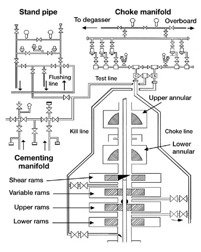
when monitored via the upper kill line (UKL). Fig. 2 shows a schematic
of the subsea BOP stack at the time of these operations.
 |
|
Fig. 2. Schematic of
subsea BOP stack at the time the well control problems
developed. |
|
An attempt was made to bullhead kill
mud down the 5-in. by 9-5/8-in. annulus through the lower choke line
(LCL) while monitoring drillstring pressure on the UKL. A maximum
surface pressure of 4,300 psi was applied to the annulus, while no
change was observed on the drillstring. A similar attempt was made to
bullhead mud down the drillstring through the UKL while monitoring
annulus pressure. A maximum of 6,050 psi was applied, but annulus
pressure remained steady. An insignificant volume of mud was injected
during this procedure.
The behavior of the well during the
kill attempts led the well control team to the following conclusions:
- Bridging in the annulus was
indicated by the lack of communication between drill pipe and
annulus (bridge most likely to be below the 5-in. liner top).
- Source of pressure in the annulus
was probably a leaking liner top.
- Source of pressure in the
drillstring was probably from communication with a high-pressure,
permeable zone below the end of the tubing string.
- It was not possible to bullhead kill
weight mud with reasonable and safe surface pressures.
A number of safety and
reliability-related issues were evaluated to determine the best
forward plan. Among the issues discussed were:
- Continued pumping operations would
involve pressures close to test pressure of the subsea BOP stack.
- Continued cycling of the fail-safe
valves could lead to serious complications and/or catastrophic
failure.
- The probability of success using
lubrication and/or bullheading techniques was very low.
- The disruption of a bridge in the
annulus could result in very high sustained surface pressures and/or
underground flow.
After thorough consideration of the
various possibilities, it was agreed that the safest, most reasonable
plan with the highest probability of success was the application of
snubbing equipment and related services. The snubbing unit would be
used to tie-back the drillstring and provide a means to establish
circulation at or near bottom.
The monsoon season in the Arabian Sea
was approaching, and since it was not be feasible to initiate well
control operations immediately, the project was scheduled for the
post-monsoon season. The well was temporarily abandoned in its current
condition. A check valve was placed in the hydraulic line connected to
the closing chamber of the SBR. This was done to trap the closing
pressure on the SBRs while preparations for the snubbing project were
made. The hydraulic connector below the upper annular was unlatched,
the drilling riser and lower marine riser package (LMRP) were removed
and the drillship was released from location.
WELL CONTROL PLANS
Thorough planning is necessary for the
safe, timely completion of any major project. However, several factors
made precise planning an absolute necessity for the B-24-2 project. A
number of individual tasks were identified and subsequently used to
develop a scope of work and schedule for the project. Some of the
major items included:
- Most suitable rig and safeguards
against punch-through risk
- Rig positioning over subsea wellhead
- Best method/ equipment to tie-back
the subsea BOP stack to the jackup rig
- Additional BOPs, pressure control
equipment and configuration
- Detailed equipment and services list
- Mobilization plan.
Rig selection and punch-through.
The potential for a punch-through occurrence made proper rig
selection a critical component of the planning stage. An intense
evaluation of all movable offshore drilling units (MODU) located in
the immediate area was undertaken. The evaluation concluded that the
most suitable rig for the project was the ONGC jackup Saga
Shakti. ONGC and third-party personnel inspected the designated
vessel.
A number of modifications were
specified to prepare the rig for the well control operations. Deck
load characteristics were addressed by removing all unnecessary
equipment. A detailed analysis of loads that would be imposed during
snubbing was performed. These loads included both static equipment
weight and dynamic loads that would occur during operations (i.e.,
tensioning riser, pulling on pipe, etc.).
Rig positioning. Placement of
the jackup rig over the subsea well was critical. The possibility of
impacting the pressurized wellhead could have catastrophic
consequences. Thus, extraordinary planning was done to minimize the
possibility of such an occurrence. The positioning plan was developed
in conjunction with, and approved by, the Warranty Surveyor. A summary
of the positioning plan follows:
- Attach marker buoy to subsea BOP.
- At 100 m, pin down legs and set four
anchors per pre-determined pattern, start moving in using anchors.
- At 50 m, install side scan sonar
(starboard/aft spud can) and acoustic tracking system (transponder
on wellhead, transducer on port/aft spud can).
- At 20 m, interchange transponder and
transducer.
- Position rig to within 6 2 m and
jack up to zero air gap.
- Check position relative to well with
diver, adjust if/as necessary.
Once positioned, the rig was pre-loaded
per water depth, environmental forces and calculated variable deck
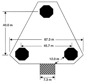
load and hook loads. The rig was then proof-loaded to capacity. Fig. 3
shows the position of the Sagar Shakti relative to the
wellhead.
 |
|
Fig. 3. Placement of
the jackup rig over the subsea well was critical since the
possibility of impacting the pressurized wellhead could have
catastrophic consequences. Anchors, side scan sonar,
transducers and transponders, and divers were used to position
the Sagar Shakti relative to the wellhead. |
|
Subsea tie-back. The 266-ft
water depth made it necessary to use specialized equipment for
reconnecting to the subsea BOPs. The riser between the subsea and
surface BOPs would have to be capable of withstanding severe combined
stresses caused by pressure, tension and bending moments. Since
ordinary API flanges are normally de-rated when this type of combined
stress is applied, a specially fabricated, purpose-built riser system
would be used.
The major components of the
high-pressure riser system are standard API 11-in., 10,000-psi spool
sections with Steel Products Offshore (SPO) “Compact”
flanges. The SPO flanges are specially designed to withstand the
combined loading that would be anticipated on the B-24-2 project. In
fact, these flanges are designed to maintain a pressure seal under
stresses that would cause a failure in the 11-in., 10,000-psi spool
body.
In addition to the spool sections, the
riser system includes a specialized spider support system for
installation on the rig floor, clamps for supporting auxiliary choke
and kill line sections and a tension ring for lateral support from the
rig structure.
BOPs and pressure control
equipment. As with any snubbing intervention application, the BOP
and pressure control equipment configuration is critical. In addition
to being adequate for the anticipated pressures and fluids, the BOP
system must be designed to establish a high-pressure (maximum working
pressure) seal on all tubulars in the wellbore and allow operations to
proceed with the surface pressure present. This includes the
installation and removal of specific tools, considering their length,
diameter and shape. While allowing certain operations to proceed, the
snubbing BOP arrangement must also provide an extraordinary measure of
reliability and redundancy.
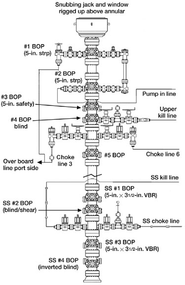
The BOP system (Fig. 4) was designed
with these factors in mind and to be independent from the existing
subsea BOPs. BOPs were arranged to accommodate all pressure testing
requirements that are associated with well control operations, as per
industry standards.
 |
|
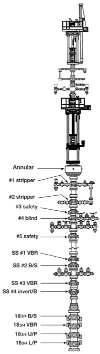
Fig. 4. The snubbing
BOPs must provide an extraordinary measure of reliability and
redundancy. Separate choke and kill lines were installed to
allow for extensive circulation. Dual valves were installed on
the subsea drilling cross for safety. Choke and kill lines
were fabricated of 5-in. drill pipe and connected to the riser
spool via special purpose clamps. |
|
Separate choke and kill lines were
installed on the subsea snubbing BOP stack, since it was anticipated
that extensive circulation would be required after the drill pipe was
tied back. The choke and kill lines allowed circulation without
sustained pressure on the riser spool. Dual valves (one HCR and one
fail-safe) were installed on the subsea drilling cross for safety.
Choke and kill lines were fabricated of 5-in. drill pipe and connected
to the riser spool via special purpose clamps.
Equipment and services. Since
snubbing operations are rarely undertaken in the region, virtually all
snubbing and auxiliary equipment had to be mobilized from the U.S. for
the project. To minimize planning difficulties, ONGC requested that as
much equipment and services as possible be supplied via a single
source. A detailed equipment and services list, along with a scope of
work, were developed and sent to three snubbing companies in the form
of a request for bids to act as general contractor for the project.
The equipment and services to be supplied by the project general
contractor included:
- Snubbing unit (400K minimum) and
related support equipment
- BOP/pressure control equipment and
specialist personnel
- High-pressure riser equipment and
specialist personnel
- Fishing tools and specialist
personnel
- Tongs and tong operator
- Slickline equipment and operator
- Wireline set bridge plugs for all
pipe strings.
ONGC supplemented personnel and
equipment requirements by supplying:
- Rig and rig support duties
(catering, crew change, etc.)
- Electric wireline services
- Pumping personnel and equipment
- Cementing and drilling fluids
personnel, material and equipment
- Communications
- Diving support personnel
- Marine vessels.
Other services, such as non-destructive
testing (NDT), specialty fabrication, machine work, etc., were also
obtained locally.
Mobilization planning. The
temporary import of the massive amount of equipment was a monumental
logistical challenge. The process was divided into two distinct phases
– loading and airfreight to India, and offloading, customs
clearance and inland transportation to the wellsite.
The first phase was arranged by the
general contractor. Transportation involved the airfreight shipment of
over 496,000 lb of equipment, plus the timely arrival of specialized
personnel. Arrival of the equipment and personnel was coordinated with
the end of the monsoon season and the mobilization of the jackup.
Customs clearance and inland equipment
transportation was performed without incident and all equipment
arrived at the rig per the mobilization plan.
PROJECT IMPLEMENTATION
The operation began with a thorough
inspection of the existing subsea BOP stack. The inspection was
performed and no leaks or other anomalies were found.
Rig-up. The first step in
installing the snubbing equipment and high-pressure riser was to
remove the upper annular from the existing 18-3/4-in. subsea BOP
stack. This annular had a maximum working pressure of 5,000 psi and
had to be removed to provide access to the 10,000-psi-rated Cameron
(CIW) 27 hub connection below it. The following procedure was used to
remove the annular BOP:
- Pick up one joint of 5-in. drill
pipe pin end first.
- Install inverted 5-in. drill pipe
elevators onto box end of drill pipe joint.
- Attach slings to eyes of elevators.
- Lower the first joint of 5-in. drill
pipe (upside down).
- Install 4-1/2-in. IF box to box
crossover.
- Run in hole with 5-in. drill pipe to
top of annular BOP (as confirmed by diver).
- Position rig cantilever exactly over
annular and attach slings to BOP.
- Pull 10,000 lb.
- Install two, 10-ton come-a-longs
from BOP bonnets to BOP frame.
- Remove top ring from annular (remove
with rig air hoist).
- Disconnect CIW 27 hub connection.
- Lift annular BOP clear of subsea
stack and raise to water surface.
- Position dynamically positioned dive
vessel under annular.
- Set annular onto deck of dive vessel
and disconnect lift slings.
The annular BOP was removed according
to plan, although some problems were encountered accessing the shuttle
valve assembly on the annular as it was positioned behind the kill
line stab lock ring. This required removal of the upper portion of the
kill line and the kill line hydraulic stab.
Installing HP riser and BOP. Before
installing the high-pressure riser, the 5-in. drill pipe sections that
would serve as the choke and kill lines were run in a conventional
manner through the rotary. Once required lengths were in place, they
were suspended from the main deck using cables and pad eyes that had
been installed for that purpose. Each section of drill pipe had 3-in.
steel hose connected to the lower end. These hoses would connect the
choke and kill lines to the drilling cross once it was in place.
The subsea BOP stack was first
assembled in three sections on the deck of the jackup. The bottom
section of riser was picked up and lowered through the rotary, and the
drilling package was skidded over the main deck so the lower riser
connection could be made up onto the existing section of the BOP
stack. This section of the BOP stack accompanied the riser section so
that the drilling package could be positioned over the middle BOP
section. The flange connection was made up and the process was
repeated for the third (lower) BOP section. The drilling package was
then repositioned and the entire assembly was lowered. Once the first
riser section was run, subsequent riser sections were picked up from
the deck and installed in a conventional manner using a special spider
assembly and elevators.
Divers confirmed that the bottom
connection of the riser/BOP stack was approaching the upper connection
of the existing subsea BOP stack. Helmet-mounted and hand-held subsea
cameras were used along with additional audio/ video units on the rig
floor to monitor the lowering of the riser assembly until the two
halves of the CIW 27 clamp were mated. Divers then tightened the CIW
27 clamp with hydraulic wrenches, connected choke and kill lines to
the drilling cross and attached the 5-in. drill pipe lines to the
riser sections. The riser was tensioned to 250,000 lb. (about 50,000
lb over-pull) and this load was then transferred to the spider
assembly on the rig floor.
Snubbing unit and surface BOP. With
the riser installed, the snubbing unit and surface BOP equipment was
rigged up in a conventional manner. Fig. 4 shows the snubbing BOP
arrangement.
Testing. A detailed testing
procedure was developed, and all pressure control components (with one
exception) were tested to 250 psi and 9,000 psi. Pressure tests were
performed by closing the inverted blind rams on the bottom of the
11-in. subsea BOP assembly. These rams were placed in this position
specifically for testing purposes.
The one exception was the CIW 27 clamp
connection where the additional (11-in.) subsea BOPs were connected to
the existing (18-3/4-in.) subsea BOPs (i.e., below the inverted blind
rams). This connection could only be tested to 5,000 psi, at which
point the SBRs would leak due to the pressure differential applied
from the top. Water-soluble oil (which has a very visible white color
in water) was used to test this connection, while subsea cameras on
the BOP stack were used to ensure that the leak was through the ram
and not from the connection itself.
WELL CONTROL INTERVENTION
Intervention was initiated by opening
the 18-3/4-in. SBRs. Drill pipe pressure was 4,250 psi. Attempts were
made to lower this pressure by lubricating mud, but this did not yield
significant results.
The top of the sheared drill pipe had
to be milled to allow access by the high pressure pack-off overshot
that could be used to tie back the drillstring. The 18-3/4-in.
variable bore rams (VBR) were opened so that milling could be done on
the top portion of the sheared drill pipe. Milling was started using
5-in. drill pipe with 4,250-psi surface pressure. Leakage occurred
during the milling process (stripper ram leakage), which caused
surface pressures to increase dramatically. However, these ram leaks
did not pose an unmanageable safety threat. Surface pressure increased
to 6,500 psi following several complete ram seal failures. Only 6 in.
were milled off the top of the drill pipe before surface pressure rose
to an unacceptable level. An additional 8 in. would have to be milled
to allow the high-pressure (10,000 psi) pack-off overshot to properly
“swallow” the drill pipe.
 |
|
Fig. 5. After several
failed attempts to set a bridge plug using wireline, it was
decided to install a second, smaller snubbing unit onto the
drill pipe. This 150K unit used 1-1/4-in. macaroni tubing to
clean out the drill pipe/ tubing string to a depth of 9,600
ft. |
|
The milling work created an ID at the
top of the sheared drill pipe that was at least as big as the ID of
the 5-in. drill pipe tool joint. Thus, a decision was made to set a
wireline bridge plug in the bottom of the tubing string. This would
allow a reduction in the surface pressure, assuming the tubing string
was intact (as expected from earlier operations).
Several attempts were made to run in
the hole with electric line. Each attempt was unsuccessful due to the
condition of the mud (which had not been circulated for several
months) and the extreme surface pressure. After a thorough evaluation
of the available options, it was decided that the best course of
action would be to install a second, smaller snubbing unit onto the
drill pipe. This 150K unit would use macaroni (1-1/4-in.) tubing to
clean out the drill pipe/ tubing string.
Fortunately, this contingency had been
discussed during the project planning, and a small snubbing unit,
along with necessary BOP equipment, tubing string and handling tools,
was mobilized from the U.S. in a remarkably short time. Operations
were temporarily suspended while the additional equipment was
transported.
Once at the wellsite, the small
snubbing unit was rigged up, tested and running pipe in less than 48
hr, Fig. 5. The 1-1/4-in. tubing was used to clean out the combination
drill pipe/ tubing string to a depth of 9,600 ft. Seawater was used to
displace the old drilling mud in the drill pipe/ tubing string. Once
the pipe string was circulated clean, seawater was displaced with
11.6-ppg CaCl 2 . This reduced surface pressure to 2,500 psi. The
1-1/4-in. tubing was removed and the 150K snubbing equipment was
rigged down.
A second attempt was made to set the
bridge plug with wireline. This time, surface pressure was only 2,500
psi and there was clean brine in the pipe string. The bridge plug was
set in the bottom joint of the 3-1/2-in. tubing and surface pressure
was bled to zero in 500-psi increments.
All surface pressure was now contained
below the 18-3/4-in. subsea pipe rams. This allowed the milling to be
continued with no surface pressure. An additional 8 in. was milled
from the top of the sheared drill pipe. This allowed the high-pressure
pack-off overshot to be latched onto the 5-in. drill pipe and tested.
With the pack-off overshot in place,
the drill pipe and annulus were isolated. Communication could be
reestablished once a flow path was developed. The drill pipe was
tensioned to the previous string weight and the 18-3/4-in. subsea pipe
rams were opened. Initial annulus pressure was recorded at 3,200 psi.
As expected from earlier operations,
the drill pipe/ tubing string was stuck due to bridging in the
annulus. While attempting to get a preliminary idea of the stuck point
via stretch measurements, the 3-1/3-in. tubing string parted at 1,657
ft. Since annular bridging was apparent and deep (based on preliminary
stretch data), it was decided to attempt bleeding the surface
pressure. The surface pressure was bled to zero in 250-psi increments.
It was decided that the safest and most
economical solution would be to abandon the B-24-2 well with cement
plugs. The 3-1/2-in. tubing fish was removed and the tubing was milled
off and re-latched. Circulation was established by perforating the
3-1/2-in. tubing at 6,004 ft. The well was circulated at this depth
with 14.0 ppg mud. A significant amount of gas was removed from the
annulus, but the well remained static after circulating.
The first abandonment plug was set 656
ft inside the tubing and in the tubing/ casing annulus from 6,004 ft
to 5,348 ft. The plug was subsequently tested to 3,500 psi after being
allowed to set.
A second balanced cement plug was set
from 1,549 to 1,220 ft and similarly tested. Finally, a wireline-set
bridge plug was set in the 9-5/8-in. casing at 1,148 ft.
CONCLUSIONS
The B-24-2 well represented a massive
technical and logistical challenge. The rare circumstances of the
situation required a unique combination of technical expertise to
develop and implement the safest and most economical solution.
Personnel from ONGC and third-party specialists had to rely on their
extensive experience in order to adapt existing technology to an
unusual and potentially dangerous situation.
The possibility of catastrophic failure
existed on several levels during the entire well control project. The
consequences of such a failure remained paramount throughout the
planning and implementation of the solution. The authors believe that
a critical, complex project such as the B-24-2 intervention can only
be performed safely and successfully when there is an exceptionally
cooperative well control and engineering effort on the part of the
operator and specialist contractors involved. 
THE
AUTHORS |
 |
David Barnett, engineering
manager for Wild Well Control, Inc., has over 20 years of
drilling, snubbing, coiled tubing and well control experience. He
has been involved with the planning and implementation of numerous
relief well and high pressure snubbing and well recovery
operations. He also has been instrumental in the development of
blowout contingency plans (BCP) for a large number of operators
ranging from small independents to multi-national corporations. In
addition, he is involved in all aspects of engineering division
projects including platform design, dynamic well-kill modeling,
training and research into improved well control equipment and
techniques. Mr. Barnett earned a BS in mechanical engineering from
the University of Houston, and he is a member of SPE, API, AADE,
ASME and IADC. |
|
|
|
D. C. Tyagi, a mechanical
engineer, has worked in India's Oil & Natural Gas Corp. (ONGC)
for the last 19 years. He is a member of the Crises Management
Team of ONGC and has been associated with almost all difficult
well situations in ONGC. He is currently working as a chief
engineer in the Mumbai Regional Business Centre and looks after
operations of the drillship Sagar Bhushan. |
|
|
 |
A. K. Mehra, a mechanical
engineer, joined ONGC in 1969 and since then has been working on
various assignments including supervising drilling and workover
operations in deep wells. He is credited with many pioneering
projects such as upgrading the drillship Sagar Vijay for deep
water drilling. He was associated with well control operations on
the subsea well, B-24-2, and is currently general manager
(Drilling) and head of the Drilling Business Group in the Mumbai
Region of ONGC where 20 offshore rigs are operating. Mr. Mehra's
ME degree is from Punjab University, and he also holds a law
degree and an MBA. He has authored many R&D articles. |
|

