New technologies resolve field operations/ management problems
TECHNOLOGY AT WORKNew technologies resolve field operations / management problems
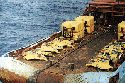
Three offshore-oriented articles address various technical challenges from designing platforms to installing newly designed anchors for mooring floating vessels in deep water. Two other features discuss a new subsea intervention tree and a case history of its application; and the use of a time / money saving logging tool to evaluate gravel packing effectiveness is introduced. A fifth presentation tells how a major operator inventoried its potential computer / controller problems in offices and fields, and what preventive measures they are taking. The presentations include: 1) Texaco's action on the Year 2000 problem, 2) How 3-D software increased platform design capability, 3) Evaluating frac packs with washpipe-conveyed logging tool, 4) Recent application of a new subsea intervention tree, and 5) The world's first taut-leg mooring using vertical loaded anchors (VLAs). Texaco takes action on Year 2000 problemHarry Woodstrom, Vice President, Consulting Services, SIG, Inc., Houston While debate continues to shadow the Year 2000 (Y2K) issue, more and more oil industry companies have recognized the potential consequences and taken action. They have inventoried their particular situation, assessed the results and committed corporate resources to have mission-critical systems Y2K compliant by January 1, 2000. One of those companies is Texaco, which concluded that every time-processing device, from mainframes to control systems, may potentially fail. Many computer applications written in prior decades, and using two-digit years to conserve data storage space, may "read" 2000 as 1900, or as "invalid." Even conservatively forecast, adverse effects on business operations could be enormous. Worldwide, Texaco's commitment (upstream and downstream) to Y2K compliance will cost about $75 million, absorbed by each operating unit's budget. Geographically, each business unit manages its respective Y2K project. In Houston, the Exploration and Production Technology Department (EPTD) and Global Information Services (GIS) jointly determined in 1997 that the time to move ahead had arrived, and retained an outside Y2K consultant for the inventory, assessment and remediation project stages for EPTD. That group of 340 scientists, engineers and support personnel is responsible for technology development and deployment to Texaco's worldwide E&P operations. Background, Texaco's commitment. "Y2K was not theoretical to us. It's all too real," says John Roberts, Texaco Y2K Coordinator at EPTD. "In reservoir analysis programs, we had cases of models being built, running smoothly, then reaching the year 2000 and reverting to 1900." In other cases, such as monitoring systems, the problem is not as obvious. The device may not display date / time. Yet some of the controllers, processors, or other components contain dates. These devices need to be inventoried and remediated or replaced. For a project with no precedents, Y2K problem resolution varies among companies. However, commonalities exist. For example, "mission-critical" generally refers to environmental, safety and health, followed by business impact, and typically centers on: hardware (mainframe, client / server and desktop), applications, telecommunications, and embedded systems. Two examples of embedded chips in operating field systems are illustrated in Fig. 1 and Fig. 2. Similarly, a Y2K project typically involves three steps: risk discovery (including inventory), problem evaluation and planning, and solution implementation (including testing). "At Houston's EPTD business unit," says Roberts, "By 1997, we had taken care of most of our mainframe applications, identifying which had potential problems and which didn't. So, our emphasis shifted to embedded systems." "Our first issue involved whether we could bring in a Y2K consultant to do meaningful work. Clearly, we could," Roberts continues. The consultant team consisted of a project manager, applications specialist, and embedded systems and networking specialists; and an initial emphasis on developing the project plan and project deliverables turned out productively. "In Y2K projects, it's easy to get diverted a million ways. This discipline kept us on track," says Carl Roecker, with Texaco's GIS. Defining the problem, taking inventory. At EPTD, Texaco scientists are empowered with limited structure, primarily relating to budget and management support. That corporate environment produces excellent results balanced with difficult-to-access equipment inventories. Specifically, applications and embedded systems were an inventory unknown, compared with PC inventories which are electronically tracked via user log-ins. Therefore, key people in the organization had to be surveyed to determine the inventory susceptible to the Y2K problem. Initially, these individuals were identified, then interviewed by the Y2K consultant manager and Roberts. The purpose was to see how they would approach obtaining the necessary information prior to development and distribution of the actual surveys. Follow-up interviews were also conducted, with an emphasis on due dates. EPTD is divided into 20 portfolios, which are research organizations working on projects in specific areas, such as improved reservoir recovery or multiphase production technology. To complicate matters, "Some portfolio managers said they already had Y2K-relevant items inventoried, just send them the survey. Others said to survey the point manager in, e.g., systems support or procurement. Or five people in one area may have five different types of involvement, so send one to each," says Y2K coordinator Roberts. Vendor software survey. As forms were received, they were evaluated, and some were reworked to ensure that all questions were answered. Then, apart from the internal survey, vendor letters were generated to determine their respective Y2K compliance. Although some EPTD software is written in-house, the majority is third-party written. So, in each instance, Texaco looked first to the vendor to state whether is was compliant or not. Some internally-written software did require a line-by-line code search, which discovered a couple of instances of compliant software interfacing with two-digit codes (corrected accordingly). Significantly, a stand-alone device may be compliant, but when multiple stand alones communicate with each other, a failure may occur if different vendors are involved. Slower than anticipated, the vendor letter process stretched from the EPTD-requested three-week response to nine months for many vendors. That time lag included receiving not only vendor responses but definitive vendor answers as well. In June 1998, a major vendor stated it was just beginning its Y2K process. In many instances, most of the expensive software is on maintenance contracts. So, Texaco receives the Y2K "fix" as part of a new release for which it contracts. Establishing priorities. Overall, the inventory stage is vital to clearly see what is at risk. Next is prioritization, risk analysis of which areas are most important. According to Roecker, on the Y2K issue, Texaco places EHS factors ahead of the impact on income. "Plants are a case in point. Most systems at refineries are monitoring systems and usually work fine. Some may not display time / date but, at worst, may cause unit shutdown. However, leaving one device unchecked could disrupt the entire operation." Therefore, the importance of evaluation and testing cannot be overstated. Yet sometimes, neither can be done, as with a bottomhole monitoring system on an offshore platform. Also, assessment is a function of who performs it. An engineer concerned with design may evaluate one way and a technician another way. Also, some software may be used only by one individual, thus having minimal impact on the organization. Conversely, most software is used by many individuals and assumes a larger importance based on impact. For that reason, it is important to employ a uniform risk analysis model, both in terms of what needs to be addressed and toward completing the project. Taking action, remediation. In the final stage of the project, Texaco and its Y2K consultant acted on the inventory and assessment results by performing remediation or replacement of non-compliant Y2K items. Ultimately, Roecker says, "Everyone needs an evergreen process, to ensure that noncompliant elements are not reintroduced. In other words, you can't stop because you have completed the inventory. You have to continually monitor the process to prevent reintroduction." Mergers and acquisitions speak directly to this issue. As a new entity and its pieces are absorbed, it is critical to make sure the merger will not disrupt Y2K resolution by bringing noncompliant elements with it. Above all, upper management must support the Y2K process, a decision made less easily in light of low mid-1998 oil prices. Yet, the repercussions are too high to risk having to look back on January 1, 2000, and ask why Y2K was not addressed and fixed. One way in which Y2K solutions are moving ahead is through information sharing among oil companies. An industry group task force that meets every six weeks has shot up in attendance recently, according to Roecker. And that is no surprise; when 1999 starts to close, there is a real chance that the Y2K issue will affect every company's tactical and strategic plans. It's a business problem, not an Information Technology (IT) problem per se, concludes
Roberts. And that problem is well on its way to companywide solutions at Texaco's EPTD and
GIS in Houston, as well as worldwide. 3-D software boosts offshore platform design capabilityPaul Anthony, Consultant, Anthony Design Services, Bakersfield, California Using manual drafting methods, Unocal Thailand was adding two or three new offshore drilling platforms each year to its natural gas fields in the Gulf of Thailand. By converting to the 3-D plant design system, AutoPLANT, from Rebis, Walnut Creek, California, the company increased this to 8 to 11 platforms annually, with only a slight increase in its design staff. The company's piping designers, who formerly needed 600 to 800 hr to prepare new platform drawings, now complete them in 80 to 160 hr, not including time spent on developing specification data and model base. The new design system, which works on top of AutoCAD, improves productivity by using a 3-D model as a project foundation. From the model, piping designers now generate isometric drawings virtually automatically. Bills of materials are also generated quickly through the software's link to a textual database. Platform expansion, demands on designers. With more than 60 offshore drilling platforms already in place in 1994, Unocal Thailand planned a significant expansion of its natural gas production over the next five years. The company expected to build about 35 new platforms in that time. Most of the platforms are of the same basic design; structures vary only slightly, depending on water depth. Most instrumentation and electrical equipment has been standardized. And most of the topside design work required to create a new platform involves piping, which is handled at Unocal by a department of four people. The piping requirements for a new platform depend on its location in the field. At the field's edge, the platform will normally have a single 10-in. export line central to a processing facility or another wellhead platform. Platforms in other locations within the field may have entirely different piping configurations. The exact configuration depends on the number of incoming and outgoing pipelines. The exact combination of incoming / outgoing pipelines is thus field / location dependent, but normally varies from a single export line to three or four incoming and one or two export lines. For each platform, the design team creates two sets of piping drawings — one for bid, another for construction. A complete platform set contains more than 550 drawings. Using manual drawing methods, three platforms were built each year, with a typical set of 292 piping drawings taking 600 to 800 hr to prepare. The increased development program, however, required that 8 to 11 platforms per year be engineered, constructed and installed. Office automation boosts production. To enable the piping design department to handle the planned increase in platform construction, the company began a major drawing office automation project, introducing the AutoCAD / AutoPLANT system in mid-1993. Unocal chose these software packages because the latter adds the specific, time-saving functions needed for plant design to the well-known CAD package, from Autodesk, Inc., Sausalito, California. AutoPLANT's use of 3-D design and its link to a textual database was the key to improving the piping designers' productivity. Another major factor for going to CAD was the repetitive nature and similarities between wellhead platforms. The major components requiring development time of the specs and model are nearly identical for each platform. Thus, it was believed that CAD would be a very effective option.
The new system's 3-D capability makes a dramatic difference in productivity because, once a 3-D model is complete, drawings can be generated quickly from the model. Unocal requires three types of drawings for piping — plan, sections and isometric — which are used for pipe fabrication and assembly. In a typical bid package, there are 12 Process & Instrumentation Diagrams (P & IDs), eight plan drawings, seven sections and 200–250 isometrics. Isometrics are the most difficult to produce manually because the designer has to mentally add the third dimension. The company is using the new system's P & ID module to draw all the sheets for each type of platform module. For each new platform design, they simply select the appropriate module sheets, then go into the software and change the title block. P & IDs describe the basic flow of natural gas through the platform and establish pipe sites and sizes of construction materials. Plan and section drawings are produced in true 3-D format. Rather than simply entering elevation data on the drawing as before, the elevation becomes an integral part of the drawing so that it can be viewed from the front or any other angle to check clearances and fits, i.e., clashcheck. This is important because of the confined nature of offshore work, with its compressed space and potential for interferences. Significant time savings. The time required to develop the 3-D model was about the same as the time previously required to produce orthographic layouts. The significant time savings with the 3-D model approach was the isometrics. Since the new system's model already contains the third dimension, producing isometrics is done almost automatically by simply blocking off the symbols which are to be included. Additional time savings come from linking orthographics and isometrics. When design changes inevitably occur, they are entered in the orthographic drawings and automatically rippled through the related isometrics. It is now easier to check the isometrics using the new system as well. Interferences can be easily detected by rotating the 3-D model into different perspectives, and using a clash detection feature. The now-feasible link to a text database provides equally significant time savings. Designers have been freed from the need to enter descriptions on the drawings. Instead, a secretary types the specs for each component into a simple flat-file textual database. After this initial information is entered, only modifications need to be entered into the database. Whenever a symbol is entered into the drawing, the textual information is automatically linked to the drawing. This information can then be used in reports such as the bill of materials, valve / specialty / instrument lists and line designation schedules. Data can be manipulated to save engineering time, such as by separating stainless steel components onto a different report or subtracting the length of in-line components to provide cut-length data. If an error is discovered in a spec, it can be corrected simply by typing the correct data into the database. The change is automatically updated, throughout all drawings. The conversion from manual drafting and bill of materials generation to 100% AutoPLANT was
completed in late 1994, at which time, Unocal had its basic 3-D platform design in the new
system that formed the basis for all new platforms. This was a modular design so that for
any new project, designers could pick and choose various parts to ultimately create all the
new piping drawings in 80 to 160 hr. Frac pack evaluation with washpipe-conveyed logging toolFrac and pack procedures are now an everyday operational reality in the Gulf of Mexico and are becoming more of the rule instead of the exception. Many new, available technologies including improved fluids, screens, perforating techniques and 3-D designs have the potential to improve the success of these treatments. To properly evaluate a frac pack design's success, diagnostic technology which indicates proppant coverage in the formation as well as in the gravel pack must be used; the diagnostics must also be cost effective. Two major deepwater players have opted to utilize tracer diagnostic services beginning with their first frac packs on recently installed deepwater tension leg platforms. Radioactive tracer applications. Gamma ray-emitting radioactive tracers placed in the proppant or gravel pack slurry are used extensively today to evaluate stimulation treatments in both low- and high-permeability environments. The benefits of using the technology include a better understanding of fracture geometry, gravel pack quality, identification of proppant distribution, verification of fracture modeling parameters and identification of recompletion candidates. Tracers are used to measure fracture height and estimate width in both hard- and soft-rock formations. The primary use of tracer technology offshore has been to analyze proppant placement in gravel pack and frac pack completions. An algorithm calculates proppant concentration and fracture width based on gamma ray intensity and effective isotope position. A spectral gamma ray memory logging system to analyze data from emplaced tracer material has been developed by ProTechnics, a Core Laboratories Co., which allows deployment from a variety of hoisting mechanisms, including slickline, electric wireline, tubing, coiled tubing and washpipe. Additionally, the SpectraScan Imager resolves tracer material placed in the formation vs. tracers placed in the screen annulus so that gravel pack effectiveness can be quantitatively identified. Washpipe logging tool deployment. The ability to deploy the system utilizing the washpipe or workstring being used for frac and pack procedures allows for significant cost savings to the operator by eliminating rig time and production shut-in time delays, as compared to wireline-type logging operations. Washpipe-conveyed imaging of gravel pack and frac pack procedures consists of mounting the SpectraScan tool inside the last joint of washpipe below a specially designed circulating sub. An extended battery pack allows the tool to operate continuously for a week or more downhole — the tool is, in effect "idling" at the bottom of the hole, at or below the sump packer, while the pumping procedure takes place above. Even with the large volume of data (640 channels every 1.6 sec) being recorded, the tool's current memory capacity exceeds 30 hours operating time. The memory sub is run in the "off" position while going in the hole, and is switched into the "on" mode by one of the following procedures:
In either of the above initiation modes, the object is to coordinate with the pumping service company and rig crew to determine the most effective way to anticipate when the washpipe's trip out of the hole will begin and to have the recording window enabled during that time. Typically, less than 1 hour is actually needed to traverse the stimulated interval with the washpipe, so there is substantial over-capacity built into the memory module. Example application. The first successful washpipe-conveyed operation was performed for BP Exploration on the Pompano platform at Viosca Knoll in the Gulf of Mexico in late 1996. Since that date, more than 20 washpipe-conveyed imaging jobs have been performed. Fig. 1 shows tracer log analysis of gravel packed fractures and the screen annulus pack in a recent deepwater frac and pack completion. The washpipe-conveyed tracer image indicates a void in the gravel pack over the bottom 10 ft of perforations and down to the sump packer. A gravel pack neutron log, run later, verified the presence of more fluid (voids in proppant) at the base of the perforations. Due to previous experience with sand control problems, it was decided to pull the screen and re-frac the well to ensure a better gravel pack. Fig. 2 shows the results of the second operation, in which a new technique was employed. Prior to pumping the gravel pack, a small proppant slug was pumped (shown in red) ahead of the main treatment and allowed to settle or bank on top of the sump packer; the treatment was then pumped in a normal fashion. The tracer log results show that all the perforations were effectively gravel packed after the second treatment. As a result of this operation, the operator was able to prevent possible future loss of
the wellbore due to incomplete gravel pack coverage. Considerable rig time was also saved by
utilizing the washpipe-conveyed imaging tool. On small templates commonly used in deep
water, any kind of downhole operations on one well, including logging, may delay planned
operations and workovers on other wells due to the close slot proximity. With the cost of
lost production and rig time factored in, washpipe-conveyed imaging can save hundreds of
thousands of dollars on a single operation. Subsea intervention system prevents major incidentHank Glansbeek, Region Technical Manager, Expro Americas Inc., Houston As a result of the drive to deepwater exploration, and the resulting tight rig market with high dayrates, it has become critical to operate safely and cost efficiently all year round, even in the hurricane season. This requires the ability to control the well and disconnect quickly at any time, enabling the marine riser to be disconnected. Conventionally, during installation and well clean up through a horizontal or spool tree, none of this was available. To meet this need, the Expro Group introduced Subsea Intervention Systems for Horizontal Tree installation. Subsea intervention tree (SSIT) principal components. The function of the subsea intervention tree is to provide primary isolation of the vertical bore. This is achieved by dual ball valves, both of which are capable of cutting up to 2-3/8-in. coil tubing. In the event of vessel positioning problems, the well is isolated by the SSIT ball valves within the BOP stack, and the landing string is disconnected at the tree. The internal diameter of the tree varies from 5, 6 or 7 in., depending on access required to install the wireline plugs in the horizontal tree. A slickjoint will be installed below the subsea test tree, allowing BOP rams to be closed, creating a barrier on the annulus side and enabling the secondary coiled tubing cutting system to be operated in case of umbilical failure. Retainer valve. The large diameter landing strings utilized in horizontal tree operations hold a large volume of retained hydrocarbons. In the event of an emergency disconnect, the time required to depressurize the string before instigating a disconnect, and additional problems created by marine riser fluid U tubing would compromise safety. To overcome these problems, a retainer valve is located just above the shear rams. The function of this valve is to close and isolate the landing string and vent trapped pressure between retainer valve and tree to the marine riser. As the landing string is bled, the retainer valve allows riser fluid to enter the test string, displacing hydrocarbons. The retainer valve is positioned across an annular ram, enabling the annular to be closed and the secondary disconnect system to be operated in case of umbilical failure. Fig. 1 shows the SSIT and retainer valve located within the BOP stack on top of the horizontal tree. Lubricator valve. Situated in the landing string, typically 90 ft below the rotary table, the lubricator valve consists of a single well valve. Its function is to provide well isolation and allow the installation of intervention tools, etc. On application of closure pressure, the valve will support a pressure differential from above, allowing the upper landing string and surface equipment to be pressure tested. If no closure line pressure is applied, the valve will pump through with application of pressure from above allowing well kill. Surface tree. This is a mono-bore system with master and swab valves in the vertical access, and flow and kill wing valves on the side outlets. The tree provides the surface pressure control equipment. Gulf of Mexico operation example. Expro Americas Inc., part of the Expro Group, has been involved with horizontal or spool tree projects in the GOM in the last three years as a supplier of subsea intervention equipment. Operating about 25 subsea intervention systems worldwide, of which three are in the GOM, the company has performed the majority (about 90%) of all completion installations on horizontal trees. During recent operations in the GOM, it has become clear that an intervention system for horizontal trees is a necessity, not a luxury. The system was called on, for the first time, to cut coiled tubing (1.25-in. OD, 0.10-in. wall thickness) and isolate the well, to control high-pressure gas release at the rig floor during a well clean up operation. While running in the hole (1,053 ft), internal pressure in the coil was lost, causing a 6,600-psi differential across the coil at surface and collapse of the coiled tubing immediately below the injector head. This resulted in a high-pressure gas escape through the pack off seals. Attempts to re-establish the seal by running in and pulling out the coiled tubing were unsuccessful, and resulted in the coil parting and subsequently increasing the rate of gas discharge. After a failed attempt to cut the coil and isolate the well by closing the CT shear and blind rams, the decision was made to close the SSIT. A "text book" closure of the upper ball valve resulted in the coiled tubing being cut, an immediate reduction in gas release and, after about 20 sec, complete cessation of hydrocarbon emissions. Assuming the CT had fallen away, the lower ball valve in the SSIT was closed. Coiled tubing was fished from above the upper ball valve and, assuming the landing string was cleared, the cutting lubricator valve was closed to enable a wireline toolstring to be installed, a plug run, and the SSIT pressure tested. However, the toolstring running failed, as an obstruction was found around the SSIT. Investigation and subsequent fishing operations revealed six pieces of coiled tubing lodged at different depths in the landing string. These results indicate that the coiled tubing had met with a shoulder and actually doubled back up the string, Fig. 2. This obviously means that, with both ball valves in the SSIT, not just a single piece of coiled tubing was cut, but actually a double cut was made — as well as a single cut with the lubricator valve — resulting in multiple pieces of coiled tubing in the well. These events clearly show the value and the necessity of a subsea intervention system as,
without which, there would not have been any means of well isolation apart from subsea BOP
shear rams. This would of course have isolated the well at the seabed but would still have
released all the high pressure hydrocarbons from the landing string in the marine riser
resulting in at least a major incident, but with a potential for a more serious scenario.
World's first taut-leg mooring using VLAs installed for PetrobrasIn April 1998, Vryhof Anchors installed 12 of its Stevmanta VLAs (vertical loaded anchors) to allow spread mooring of Petrobras' P-27 semisubmersible floating production unit (FPU) in Voador field, Campos basin, in 1,673 to 1,870-ft (510 to 570-m) water. The system was installed in 12 days. The installation was the world's first VLA spread mooring, and the first-ever VLA-polyester mooring line system. Two anchor handling vessels (AHVs) were used to handle the system's installation and mooring lines; a third assisted as "back-up" to provide the required 350-mt test load after installation.
Petrobras' application. The short time involved in the anchor installation was important to the operator due to high-level activity in Campos and the resulting high-cost of installation vessels. Every opportunity to get the work done had to be utilized. The installation vessel, Maersk Battler, for example, had just returned from the P-31 installation and a rig move. The VLAs were designed to be pre-installed to form the taut-leg mooring system for P-27. The spread has a diameter of 4,592 ft (1,400 m); its12 lines are arranged in four groups of three anchors each, with 10° between the center and outside anchors in each group. From the VLA, each line comprises 100 m of 102-mm dia. wire rope, 650 m of 136-mm dia. polyester line and 250 m of 79-mm 12Q3 +20% chain. Required ultimate pull-out capacity is 699 mt, a 1.5 safety factor on maximum damaged load condition. The soil condition at the site is a "very soft clay (mud)," into which the anchors penetrated a measured 69 to 81 ft (21 to 25 m). Installation and proof loads were 252 to 330 mt and 322 to 370 mt (at 33° uplift angle), respectively. Each anchor has a surface area of 118 ft2 (11 m2).
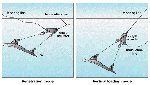
Installation procedure, the chosen installation method involved a second AHV, as Petrobras did not want to use the polyester mooring line as an installation line. Thus, for each anchor, the poly line handled by Maersk Chieftain had to be transferred to the installation vessel Maersk Battler, for the pulling test. The Far Sailor was used to give Battler extra bollard pull for the testing. The 11-m2 VLAs were configured for a two-line installation. An installation line (comprising wire rope and chain), and the mooring line (comprising polyester and wire rope) were both connected to the anchor's angle adjuster, see accompanying drawing. The design of the angle adjuster and the wire ropes connecting the adjuster to the fluke plate allows the angle of force applied to the plate to be changed, depending on which line is used for pulling. When force is applied to the installation line, the anchor is oriented in the optimal angle for penetration. After installation load has been reached, the installation line is slacked off and the mooring line is tensioned. Due to the mooring line being tensioned, the fluke plate will rotate in the soil until the resulting force is normal to the plate. The anchor is now in the normal (vertical) loading mode. A typical installation procedure went like this:
The first anchor was installed on April 4; 11 days later the full mooring spread had been installed and tested at up to 350 mt. In conclusion, the installer says the VLA installation, using two lines, required about the same time as a conventional spread. The use of the shear-pin or a breaking device is a "practical and reliable method." And the P-27 job confirmed predictions for drag / penetration for a certain load. Advantages of the VLA for taut-leg mooring systems has been demonstrated, Vryhof says. And
the developer is convinced that applications will follow in the deep U.S. Gulf of Mexico,
offshore West Africa, SE Asia and West of Shetlands. Further, they say, use of VLAs for
mobile drilling units is also viable. Copyright © 1999 World
Oil |